Structure of thermal fin with high heat conductivity and its manufacturing method
A technology with high thermal conductivity and heat sink, applied in semiconductor devices, semiconductor/solid-state device components, electrical components, etc., it can solve the problems of limited thermal conduction efficiency, inability to meet the heat dissipation requirements of higher-speed central processing units, and high proportion of copper alloy heat sinks , to achieve the effect of reducing weight
- Summary
- Abstract
- Description
- Claims
- Application Information
AI Technical Summary
Problems solved by technology
Method used
Image
Examples
Embodiment 1
[0019] The aluminum alloy adopts AlMgSi, and the composition of the aluminum alloy is:
[0020] Si
Fe
Cu
mn
Mg
Cr
Zn
Al
0.6
0.35
0.1
0.1
0.75
0.1
0.1
97.9
[0021] Silicon carbide accounts for 10% by weight of the overall heat sink, and the particle size of silicon carbide is 80 μm. The specific method is as follows:
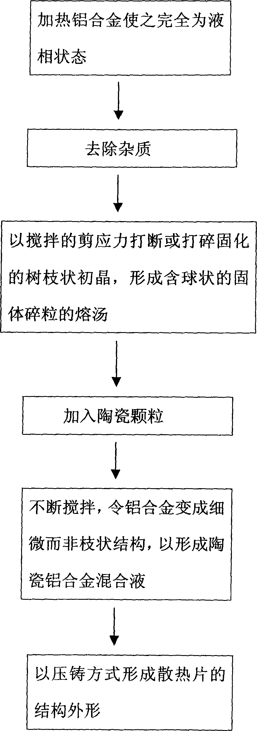
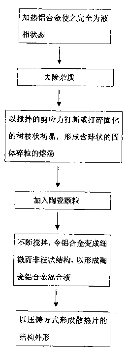
[0022] 1. Heat the aluminum alloy to 660-720°C in a melting furnace, and make sure that the aluminum alloy is completely in a liquid state.
[0023] 2. Carry out slag removal work to remove impurities in aluminum alloy.
[0024] 3. Add ceramic particles.
[0025] 4. Stir the molten soup with a stirring rod at the solid-liquid phase temperature, and keep the temperature of the molten soup at 550-700°C.
[0026] 5. Use the robotic arm to scoop up the evenly stirred molten soup and inject it into the injection system of the die-casting equipment for injection and forming. Th...
Embodiment 2
[0029] The aluminum alloy adopts AlMgSi, and the composition of the aluminum alloy is the same as that in Example 1.
[0030] Silicon carbide accounts for 25% by weight of the overall heat sink, and the particle size of silicon carbide is 120 μm. The specific method is as follows:
[0031] 1. The melting furnace heats the aluminum alloy to 660-720°C, and confirms that the aluminum alloy is completely in a liquid state.
[0032] 2. Carry out slag removal work to remove impurities in aluminum alloy.
[0033] 3. Add ceramic particles.
[0034] 4. Stir the molten soup with a stirring rod at the solid-liquid phase temperature, and keep the temperature of the molten soup at 550-700°C.
[0035] 5. Use the robotic arm to scoop up the evenly stirred molten soup and inject it into the injection system of the die-casting equipment for injection and forming. The clamping force of the die-casting machine is 200-250ton, and the casting area pressure during injection is 150-250Kg / cm 2 ...
Embodiment 3
[0038] The aluminum alloy adopts AlMgSi, and the composition of the aluminum alloy is the same as that in Example 1.
[0039] Silicon carbide accounts for 60% by weight of the overall heat sink, and the particle size of silicon carbide is 320 μm. The specific method is as follows:
[0040] 1. The melting furnace heats the aluminum alloy to 700-760°C, and confirms that the aluminum alloy is completely in a liquid state.
[0041] 2. Carry out slag removal work to remove impurities in aluminum alloy.
[0042] 3. Add ceramic particles.
[0043] 4. Stir the molten soup with a stirring rod at the solid-liquid phase temperature, and keep the temperature of the molten soup at 590-630°C.
[0044] 5. Use the robotic arm to scoop up the evenly stirred molten soup and inject it into the injection system of the die-casting equipment for injection and forming. The clamping force of the die-casting machine is 200-250ton, and the casting area pressure during injection is 150-250Kg / cm 2 ...
PUM
| Property | Measurement | Unit |
|---|---|---|
| particle diameter | aaaaa | aaaaa |
| density | aaaaa | aaaaa |
| particle diameter | aaaaa | aaaaa |
Abstract
Description
Claims
Application Information
 - R&D
- Intellectual Property
- Life Sciences
- Materials
- Tech Scout
- Unparalleled Data Quality
- Higher Quality Content
- 60% Fewer Hallucinations
Browse by: Latest US Patents, China's latest patents, Technical Efficacy Thesaurus, Application Domain, Technology Topic, Popular Technical Reports.
© 2025 PatSnap. All rights reserved.Legal|Privacy policy|Modern Slavery Act Transparency Statement|Sitemap|About US| Contact US: help@patsnap.com


