
Industrial flue gas desulfurization and purification treatment process

A technology for industrial flue gas and purification treatment, which is applied in the direction of gas treatment, grain treatment, chemical instruments and methods, etc. It can solve the problems of poor use effect of ore pulp, poor uniformity of ore powder, and easy bonding, so as to improve the desulfurization effect, Avoid mutual bonding and reduce the effect of pollution

Pending Publication Date: 2021-09-21
湖北明亿节能环保科技有限公司
View PDF3 Cites 0 Cited by
  • Summary
  • Abstract
  • Description
  • Claims
  • Application Information

AI Technical Summary

Problems solved by technology

[0003] When grinding soft ore rough ore, it is necessary to grind and sieve the rough ore and use auxiliary flue gas desulfurization purification treatment device: At present, the existing industrial flue gas desulfurization purification treatment device has the following defects: 1. Existing industrial The flue gas desulfurization purification treatment device cannot classify, grind and screen the raw manganese ore, resulting in too large ore powder particles affecting the full contact and absorption of the pulp and flue gas, affecting the flue gas desulfurization efficiency and desulfurization effect; 2. Existing industrial flue gas desulfurization purification The processing device cannot fully and evenly stir the mineral powder, which will cause the mineral powder to be easily bonded when the pulp is formed after contacting with water. The uniformity of the mineral powder in the pulp is poor, and the use effect of the pulp is poor.

Method used


Image

  • Industrial flue gas desulfurization and purification treatment process
  • Industrial flue gas desulfurization and purification treatment process
  • Industrial flue gas desulfurization and purification treatment process

Examples


Embodiment Construction

[0033] The specific embodiment of the present invention will be described in further detail by describing the embodiments below with reference to the accompanying drawings, the purpose is to help those skilled in the art to have a more complete, accurate and in-depth understanding of the concept and technical solutions of the present invention, and To facilitate its practice, but not as a limitation of the invention.

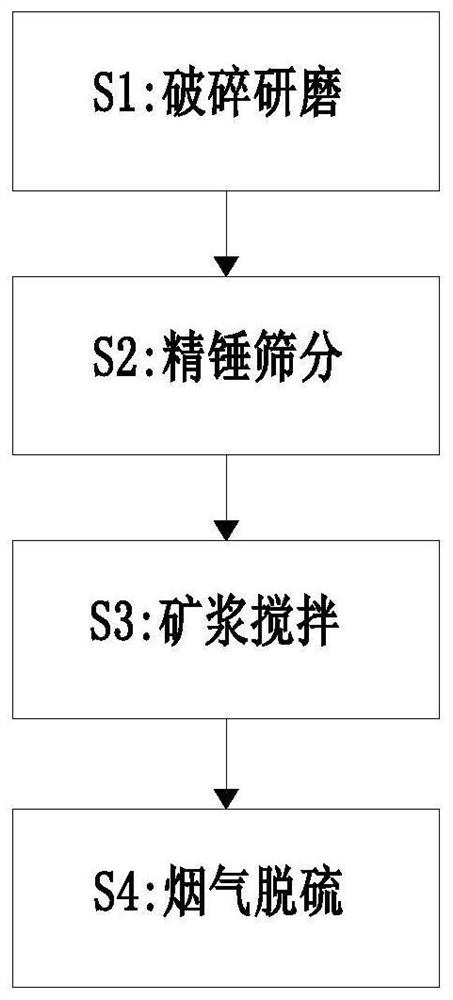
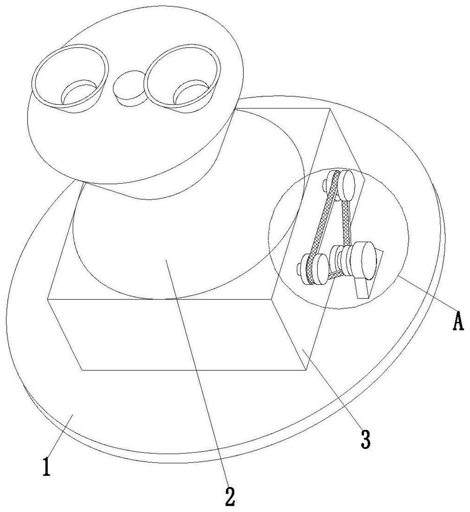
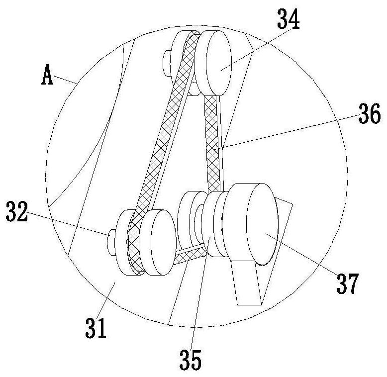
[0034] See attached Figure 1-7As shown, an industrial flue gas desulfurization purification treatment process uses an auxiliary industrial flue gas desulfurization purification treatment device. The auxiliary industrial flue gas desulfurization purification treatment device includes a bottom plate 1, an ore powder grinding mechanism 2 and an ore slurry stirring mechanism 3 , the middle part of the upper end surface of the bottom plate 1 is sequentially installed with a pulp stirring mechanism 3 and a mineral powder grinding mechanism 2 from bottom to top.

[0...


PUM


Abstract

The invention relates to an industrial flue gas desulfurization and purification treatment process, which uses an auxiliary industrial flue gas desulfurization and purification treatment device, and the auxiliary industrial flue gas desulfurization and purification treatment device comprises a bottom plate, a mineral powder grinding mechanism and an ore pulp stirring mechanism. The ore pulp stirring mechanism and the ore powder grinding mechanism are sequentially installed in the middle of the upper end face of the bottom plate from bottom to top. The industrial flue gas desulfurization and purification treatment process can solve the problems that an existing industrial flue gas desulfurization and purification treatment device cannot perform graded grinding and screening on manganese ore raw stones, so that mineral powder particles are too large, sufficient contact and absorption of ore pulp and flue gas are affected, and the flue gas desulfurization efficiency and the desulfurization effect are affected, and can also solve the problems that an existing industrial flue gas desulfurization and purification treatment device cannot fully and uniformly stir the mineral powder, so that the mineral powder is easy to adhere when the mineral powder is in contact with water to form ore pulp, the uniformity of the mineral powder in the ore pulp is poor, and the use effect of the ore pulp is poor.

Description

technical field [0001] The invention relates to the technical field of flue gas desulfurization, and specifically proposes an industrial flue gas desulfurization purification treatment process. Background technique [0002] Flue gas desulfurization refers to the removal of sulfur oxides from flue gas or other industrial waste gases. With the development of industry and the improvement of people's living standards, the thirst for energy is also increasing, and SO2 in coal-burning flue gas has become the main cause of air pollution. Reducing SO2 pollution has become an urgent task of today's atmospheric environment governance. Many flue gas desulfurization processes have been widely used in industry, and it also has important practical significance for the treatment of exhaust gas from various boilers and incinerators. The pyrolusite flue gas desulfurization resource technology is a commonly used method for industrial flue gas desulfurization. Its principle is: MnO2 is a goo...

Claims


Application Information

Patent Timeline
Patent Type & Authority Applications(China)
IPC IPC(8): B01D53/80B01D53/50B01F13/10B01F15/00B01F15/02B01F3/20B01F7/08B02C1/14B02C2/10B02C23/10B01F23/70
CPCB01D53/80B01D53/50B02C1/14B02C2/10B02C23/10B01D2251/602B01D2258/0283
Inventor 李开明
Owner 湖北明亿节能环保科技有限公司
Learn More