Layered washing method for slurry circulation system of slurry balance shield machine

A mud-water balance and shield machine technology, applied in chemical instruments and methods, cleaning methods and utensils, cleaning methods using liquids, etc., can solve problems such as increased construction costs, prolonging the construction period, and affecting construction progress, and achieve savings Construction time, restoration of shield construction, effect of restoration of mud-water circulation

Pending Publication Date: 2021-09-21
CCCC TUNNEL ENG +1
View PDF8 Cites 0 Cited by
  • Summary
  • Abstract
  • Description
  • Claims
  • Application Information

AI Technical Summary

Problems solved by technology

[0003] In order to overcome the blockage of the muddy water chamber in the existing shield machine, the muddy water circulation system is used to flush the muddy water chamber, which cannot effectively dredge the chamber, which affects the construction progress, prolongs the construction period, and increases the cost of engineering construction. The present invention provides a layered flushing method for mud water circulation system of mud water balance shield machine

Method used


Image

  • Layered washing method for slurry circulation system of slurry balance shield machine
  • Layered washing method for slurry circulation system of slurry balance shield machine

Examples


Embodiment

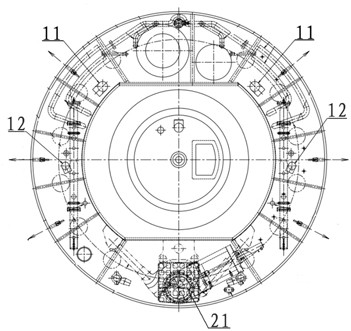
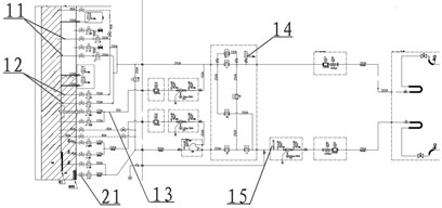
[0028] When the mud-water balance shield machine uses the internal mud-water circulation mode to flush the pipeline in the ring, the pressure sensor Ⅰ14 on the mud inlet pipe I group 11 and mud inlet pipe II group 12 shows that the pressure increases, and the mud-water circulation flow rate is 0m³ / min ;Remove the mud inlet and discharge pipelines connected to the mud tank in the ring body, and found that the mud inlet pipe group I 11 is not blocked, the mud inlet pipe group II group 12, the cutterhead center flushing pipe 13 and the main mud discharge pipe group 21 are seriously blocked; open at the same time Both the flushing pipeline and the mud discharge pipe in the center of the spare cutter head were found to be seriously blocked. According to the height of the blocked pipeline in the muddy water warehouse, it was preliminarily judged that the slag in the muddy water warehouse reached 0.5 meters above the center line. To dredge the mud tank, the steps are as follows:

[0...


PUM


Abstract

The invention discloses a layered flushing method for a slurry circulation system of a slurry balance shield machine. The method comprises the following steps that A, an air cushion cabin is circularly washed by adopting muddy water until no muck is screened; B, a cutterhead center flushing pipeline is connected to a mud discharging pipe flow divider, slurry is fed through the cutterhead center flushing pipeline, a mud feeding pipe set I discharges slurry to carry out layered flushing on slag-carried on a muddy water bin till no residue soil exists in the screening process; C, slurry is fed through a cutterhead center flushing pipeline, a mud feeding pipe set II discharges slurry to carry out layered flushing on slag-carried on the muddy water bin till no residue soil exists in the screening process; D, slurry is fed from a main mud discharging pipe set, and the mud feeding pipe set I and the mud feeding pipe set II discharge slurry at the same time to flush and carry residues in the muddy water bin till no residue soil exists in the screening process; and E, slurry is fed through the mud feeding pipe set I and the mud feeding pipe set II at the same time, slurry is discharged from the main mud discharging pipe set, slag is washed and carried in the muddy water bin till no muck exists through screening, and tunneling is recovered. The method has the beneficial effects that the blocking position of the muddy water bin can be accurately flushed, muddy water circulation is recovered, and shield construction is rapidly recovered.

Description

technical field [0001] The invention relates to a construction method for quickly recovering shield excavation from a mud-water shield machine when a mud-water chamber is blocked, in particular to a layered washing method for a mud-water circulation system of a mud-water balance shield machine, which belongs to the technical field of mud-water shield construction. Background technique [0002] Shield method tunnel construction is widely used in water conservancy and hydropower projects, urban rail transit, and highway tunnel construction. At present, when the slurry tank is blocked during the construction of the mud-water balance shield machine, the slurry circulation system is used to flush the slurry tank and carry slag, that is, the slurry discharge pipe is changed into a slurry inlet pipe and the slurry inlet pipe is changed to The slurry discharge pipe is used to dredge the mud tank. However, due to the unknown position of the slag in the mud tank and the large span of ...

Claims


Application Information

Patent Timeline
Patent Type & Authority Applications(China)
IPC IPC(8): E21D9/06E21D9/08B08B3/02
CPCE21D9/0642E21D9/08B08B3/02
Inventor 干聪豫左世荣李辉夏鹏举莫康康曹英贵张晗硕张伟周子忱孙晨辉赵世奇李皓皓
Owner CCCC TUNNEL ENG
Why Eureka
Try Eureka