Oil tank isolation valve fault diagnosis method and diagnosis system

A fault diagnosis system and fault diagnosis technology, applied in the charging system, adding non-fuel substances to fuel, electrical control and other directions, can solve problems such as unclear fault direction, stuck normally open fault, gas leakage and pump resistance reduction, etc. , to avoid unclear fault direction, improve accuracy, and avoid fault misjudgment

Active Publication Date: 2021-09-21
UNITED AUTOMOTIVE ELECTRONICS SYST
View PDF5 Cites 1 Cited by
  • Summary
  • Abstract
  • Description
  • Claims
  • Application Information

AI Technical Summary

Problems solved by technology

see image 3 As shown, when there is a certain amount of leakage between the fuel tank isolation valve and the carbon canister or between the carbon canister and the carbon canister solenoid valve, the gas leakage pump resistance decreases, which will cause the pump current in Zone III to increase slowly, and there will be no fault misjudgment It is a stuck fault of the fuel tank isolation valve; it will also cause the pump current to increase slowly in zone II. When the system has a stuck and normally closed fault of the fuel tank isolating valve, it cannot be reliably judged in zone II, and it may be misjudged as a stuck normally open fault when entering zone III , causing the fault to be unclear

Method used


Image

  • Oil tank isolation valve fault diagnosis method and diagnosis system
  • Oil tank isolation valve fault diagnosis method and diagnosis system
  • Oil tank isolation valve fault diagnosis method and diagnosis system

Examples


no. 1 example ;

[0074] The present invention provides a fuel tank isolation valve fault diagnosis method, comprising the following steps:

[0075] S1, after forming a fault diagnosis working condition, carry out diagnostic pressure self-test;

[0076] S2, pressurize the oil tank and carbon canister pipeline, and record the current variation of the diagnostic pressure source and the pressure variation of the fuel tank within the first specified period, which are recorded as ΔI1 and ΔP1 respectively;

[0077] S3, according to ΔI1 and the first specified threshold value of the current variation of the diagnostic pressure source, determine whether the fuel tank isolation valve has the first type of fault;

[0078] S4, stop pressurizing the fuel tank, continue to pressurize the carbon canister pipeline, and record the current variation of the diagnostic pressure source and the pressure variation of the fuel tank within the second specified time period, which are recorded as ΔI2 and ΔP2 respectivel...

no. 2 example ;

[0085] refer to Figure 5 As shown, the present invention provides a fuel tank isolation valve fault diagnosis method, comprising the following steps:

[0086] S1, after forming a fault diagnosis working condition, carry out diagnostic pressure self-test;

[0087] S2, pressurize the oil tank and carbon canister pipeline, and record the current variation of the diagnostic pressure source and the pressure variation of the fuel tank within the first specified period, which are recorded as ΔI1 and ΔP1 respectively;

[0088]S3, if ΔI1>a, it is determined that the fuel tank isolation valve has the first type of failure;

[0089] S4, stop pressurizing the fuel tank, continue to pressurize the canister pipeline, and record the current variation of the diagnostic pressure source and the pressure variation of the fuel tank within the second specified time period, which are recorded as ΔI2 and ΔP2 respectively;

[0090] S5, according to ΔI1 and ΔI2, determine whether the fuel tank isol...

no. 3 example ;

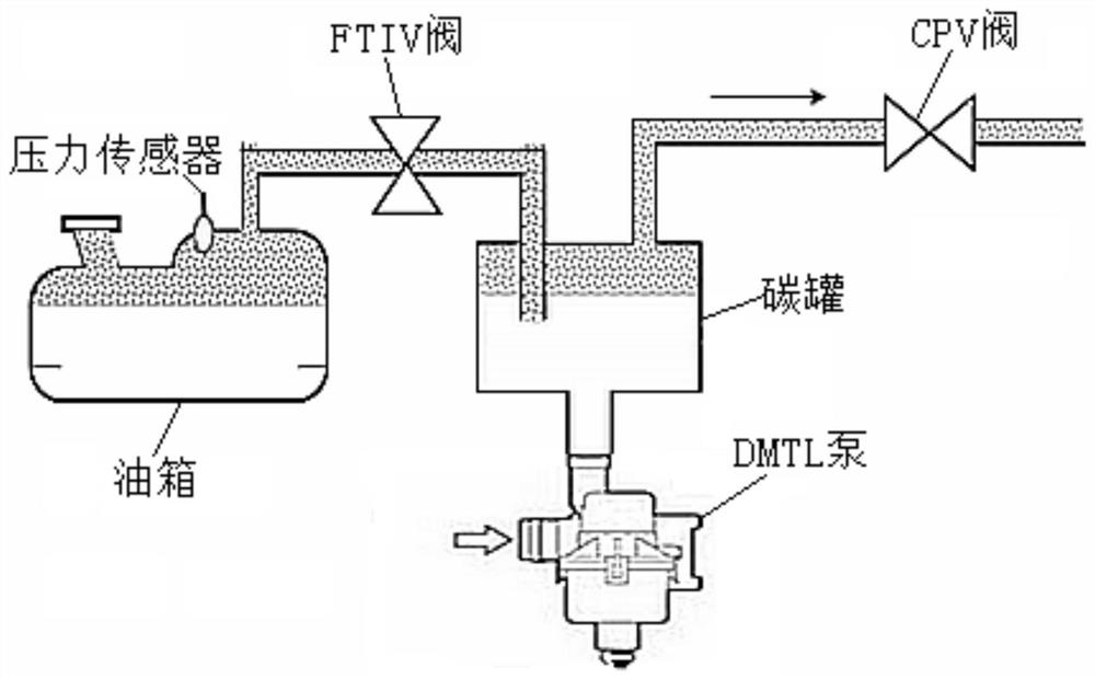
[0102] refer to figure 1 As shown, a fuel tank isolation valve fault diagnosis system includes: a pressure sensor for measuring the fuel tank pressure, which is located between the fuel tank and the carbon canister (the fuel tank isolation valve is generally integrated on the fuel tank, figure 1 The schematic diagram only shows its isolation function, so the pipeline is drawn), the fuel tank isolation valve, the diagnostic pressure source connected to the carbon tank for pressurization, the carbon tank solenoid valve located on the carbon tank pipeline, and the receiving pressure sensor and diagnostic pressure Source working parameters and control the controller (not shown in the figure) of the oil tank isolation valve, the carbon tank solenoid valve and the action of the diagnostic pressure source, the controller adopts the following steps to perform fault diagnosis; the controller can be set separately, for example, by using an MCU; or , integrating the controller with the e...


PUM


Abstract

The invention discloses an oil tank isolation valve fault diagnosis method, which comprises the following steps of: after a fault diagnosis working condition is formed, performing diagnosis pressure source self-inspection; pressurizing the oil tank and the carbon tank pipeline, and recording a diagnosis pressure source current variation and an oil tank pressure variation in a first specified time period; according to the diagnosis pressure source current variation and a first specified threshold value of the diagnosis pressure source current variation, judging whether the oil tank isolation valve has a first type of fault or not; stopping pressurizing the oil tank, continuing pressurizing the carbon tank pipeline, and recording the current variation of the diagnostic pressure source and the pressure variation of the oil tank in a second specified time period; and according to a diagnosis pressure source current variable quantity specified threshold value and a fuel tank pressure variable quantity specified threshold value, judging that no fault occurs, a first type of fault occurs or a second type of fault occurs. Misjudgment and missed judgment of the clamping stagnation fault of the oil tank isolation valve fault can be avoided, and the fault judgment accuracy is improved.

Description

technical field [0001] The invention relates to the field of automobiles, in particular to a fault diagnosis method for a fuel tank isolation valve of a hybrid vehicle. The invention relates to a fuel tank isolation valve fault diagnosis system for a hybrid vehicle. Background technique [0002] With the gradual tightening of my country's emission regulations and fuel consumption, more and more hybrid models have emerged. Hybrid vehicles can realize that under certain working conditions, the engine does not run but is directly driven by the electric motor. When the engine is not running, the fuel evaporation cannot be desorbed through the engine, and the carbon tank is likely to experience high load or even oil and gas overflow. In order to meet the requirements of National VI fuel evaporative emissions, many current hybrid projects choose the hardware configuration of "high-pressure fuel tank + fuel tank isolation valve (FTIV valve)" to prevent the discharge of oil vapor ...

Claims


Application Information

Patent Timeline
Patent Type & Authority Applications(China)
IPC IPC(8): F02D41/22F02M25/08
CPCF02M25/0818Y02T10/40
Inventor 佟娟娟徐浦星
Owner UNITED AUTOMOTIVE ELECTRONICS SYST
Why Eureka
Try Eureka