CEMS efficient purge valve device based on pneumatic control

A technology of pneumatic control and purging valve, applied in valve device, sampling device, measuring device, etc., can solve the problems of purging gas pressure relief, low backflushing efficiency, pollution of measuring cavity, etc., achieving low failure rate and simple structure Reliable and effective in solving valve blanks

Active Publication Date: 2021-09-21
北京新叶科技有限公司
View PDF5 Cites 0 Cited by
  • Summary
  • Abstract
  • Description
  • Claims
  • Application Information

AI Technical Summary

Problems solved by technology

In-situ measurement is of great guiding significance for denitrification optimization and precise ammonia injection. Since the solenoid valve cannot be installed on the probe in the high-temperature environment of the flue, the purge gas will enter the measurement chamber during purging to cause pressure relief, and at the same time cause pollution and thermal deformation of the measurement chamber Affects measurement reliability and accuracy, resulting in in-situ measurement not being widely used
In addition, the existing technology also has the following problems: 1) the blowback efficiency is low because the purge gas enters the measurement chamber and the back-end pipeline before reaching the purge area, and the blowback efficiency is low; Electronic and rubber parts cannot be used in high temperature environment, resulting in no usable high temperature switch valve; 3) In-situ measurement is of great guiding significance for denitrification optimization and precise ammonia spraying. During sweeping, the purge gas will enter the measurement chamber to cause pressure relief, and at the same time, the measurement chamber will be polluted and thermally deformed, which will affect the reliability and accuracy of the measurement, making in-situ measurement unable to be widely used

Method used


Image

  • CEMS efficient purge valve device based on pneumatic control
  • CEMS efficient purge valve device based on pneumatic control
  • CEMS efficient purge valve device based on pneumatic control

Examples


Embodiment Construction

[0021] The technical solutions in the embodiments of the present invention will be clearly and completely described below in conjunction with the embodiments of the present invention. Apparently, the described embodiments are only some of the embodiments of the present invention, not all of them. Based on the embodiments of the present invention, all other embodiments obtained by persons of ordinary skill in the art without creative efforts fall within the protection scope of the present invention.

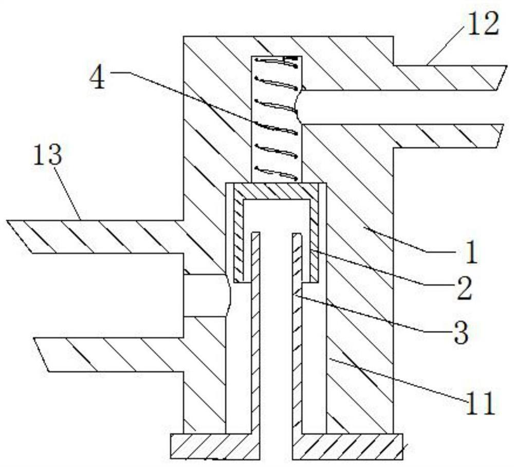
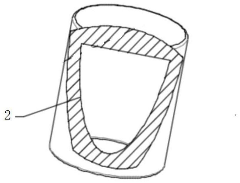
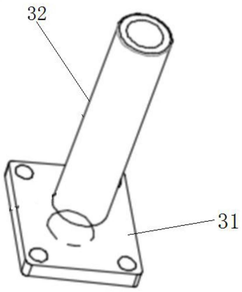
[0022] refer to Figure 1-6 , a CEMS high-efficiency purge valve based on pneumatic control includes a valve body 1, a valve core 2, a valve stem 3 and a spring 4. The valve body 1 is provided with a stepped cylindrical blind hole 11, and the blind hole 11 is divided into It is an inner cavity one 111 and an inner cavity two 112, the inner diameter of the inner cavity two 112 is greater than the inner diameter of the inner cavity one 111, the inner cavity one 111 communicates with...


PUM


Abstract

The invention discloses a CEMS efficient purge valve device based on pneumatic control. The CEMS efficient purge valve device comprises a valve body, a valve element, a valve rod and a spring. A stepped-column-shaped blind hole is formed in the valve body and divided into a first inner cavity and a second inner cavity; the first inner cavity is communicated with a measuring cavity of a sampling probe through a first through hole, and the second inner cavity is connected with a filter element or a purging area through a second through hole; the spring is arranged in the first inner cavity and the second inner cavity, the valve element is arranged in the second inner cavity, the valve element is a hollow cylinder with the top sealed and the bottom open, and the valve rod comprises a tubular structure and a flange structure; the tubular structure penetrates through a hole-shaped structure of the flange structure to be connected with the flange structure, the flange structure is plugged at the bottom of the valve body, and the outer diameter of the flange structure is greater than the inner diameter of the second inner cavity; and the valve rod is located in the second inner cavity, and when no external force exists, under the action of the gravity of the valve element and the spring, the first through hole is communicated with the second through hole, the valve element moves upwards under the action of upward force till a lower end opening of the first inner cavity is blocked by the valve element, and the valve rod is communicated with the second through hole.

Description

technical field [0001] The invention relates to a CEMS high-efficiency purge valve device based on pneumatic control. Background technique [0002] When the existing CEMS sampling probe takes samples for a long time, dust and other particles in the flue gas will easily block the sampling probe rod and filter element, etc. High frequency and high pressure purging is a must for the existing probe. The existing in-situ measurement and extractive measurement probes, the blowback valve is a solenoid valve used at room temperature, there is a certain distance between the solenoid valve and the purge area, and the purge impact force is weakened when the solenoid valve is opened and reaches the purge area. In-situ measurement is of great guiding significance for denitrification optimization and precise ammonia injection. Since the solenoid valve cannot be installed on the probe in the high-temperature environment of the flue, the purge gas will enter the measurement chamber during p...

Claims


Application Information

Patent Timeline
Patent Type & Authority Applications(China)
IPC IPC(8): F16K17/04F16K17/12F16K11/044G01N1/22
CPCF16K17/0473F16K17/12F16K11/044G01N1/2258
Inventor 杨建明郭子然高星孟召光
Owner 北京新叶科技有限公司
Why Eureka
Try Eureka