Airplane airtight cabin drain valve

A technology for airtight cabins and drain valves, which is applied to aircraft parts, lifting valves, fuselages, etc., and can solve the problems of tedious disassembly and assembly by maintenance personnel and increased manufacturing costs.

Pending Publication Date: 2021-09-21
上海极至航空科技有限公司
View PDF0 Cites 0 Cited by
  • Summary
  • Abstract
  • Description
  • Claims
  • Application Information

AI Technical Summary

Problems solved by technology

Due to the structural strength requirements of the aircraft, the fuselage is equipped with various skin thickness areas. In order to ensure the aerodynamic requirements of the outer surface of the aircraft, it is necessary to arrange a variety of drain valves with different specifications for different skin thickness areas, which not only increases the manufacturing cost, but also Bring a lot of tedious work to the disassembly and assembly of maintenance personnel

Method used


Image

  • Airplane airtight cabin drain valve
  • Airplane airtight cabin drain valve
  • Airplane airtight cabin drain valve

Examples


Embodiment Construction

[0024] The conception, specific structure and technical effects of the present invention will be further described below in conjunction with the accompanying drawings, so as to fully understand the purpose, characteristics and effects of the aircraft airlock drain valve of the present invention.

[0025]

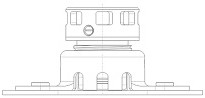
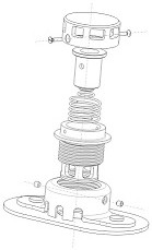
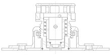
[0026] figure 1 It is an axial side view of an aircraft airlock drain valve in an open state in an embodiment of the present invention; figure 2 It is a three-dimensional structural schematic diagram of an aircraft airtight cabin drain valve in an embodiment of the present invention.

[0027] Such as figure 1 and figure 2 As shown, in this embodiment, the aircraft airlock drain valve 100 is installed at the fuselage drain hole 201 of the fuselage skin 200 at the bottom of the aircraft airlock cabin, for opening and closing the fuselage drain hole 201 state is controlled. The aircraft airlock drain valve 100 includes a mounting seat 10 , a valve body assembly 20 , a v...


PUM


Abstract

The invention provides an airplane airtight cabin drain valve comprising a valve body assembly, a valve element assembly and a mounting seat, the valve body assembly comprises a valve body with a valve cavity and at least one set screw part, the side wall of the lower end portion of the valve body is provided with at least one valve body water inlet, and the lower end face is provided with a valve body drain hole; and the valve element assembly comprises a valve element and a compression spring part. The mounting seat comprises a mounting seat main body with a valve body mounting cavity, at least one mounting seat water inlet is formed in the side wall of the lower end portion of the mounting seat main body, a mounting seat internal thread is arranged on the inner surface of the valve body mounting cavity, and a first valve body external thread is arranged on the outer surface of the valve body; and the valve body is rotatably mounted in the valve body mounting cavity in the mode that the first valve body external thread is matched with the mounting seat internal thread, at least one set screw hole is formed in the side portion of the mounting seat main body, and when the lower end surface of the valve body is flush with the outer side surface of a fuselage skin, the tail end portion of the set screw part extends into the valve body mounting cavity and is tightly pressed on the outer surface of the valve body.

Description

technical field [0001] The invention belongs to the technical field of aircraft structural design, and in particular relates to an aircraft airtight cabin drain valve. Background technique [0002] For civil aviation passenger planes, cargo planes and other high-altitude aircraft, in order to ensure the working conditions and safety and comfort of the crew and passengers when flying at high altitudes, the cabin and cargo compartment of the aircraft must be designed as pressurized airtight cabins, and the fuselage structure is sealed to ensure the safety of the fuselage. Airtightness, and through the environmental control system to ensure stable pressure and temperature in the cabin. However, it is unavoidable that due to the drastic temperature difference between the inside and outside of the airtight cabin caused by the take-off and landing of the aircraft, or rainwater entering the cargo compartment through the cargo compartment door when the aircraft is on the ground, and...

Claims


Application Information

Patent Timeline
Patent Type & Authority Applications(China)
IPC IPC(8): F16K17/06F16K27/02F16K27/12F16K1/36F16K1/46B64C1/00
CPCF16K17/06F16K27/02F16K27/12F16K1/36F16K1/46B64C1/00B64C2001/009
Inventor 刘若斯屠友林姚澎涛
Owner 上海极至航空科技有限公司
Why Eureka
Try Eureka