
A photoelectric composite connector

An optoelectronic composite and connector technology, applied in the direction of connection, optical waveguide coupling, two-component connection device, etc., can solve the problems of affecting optical signal transmission, complex operation, high cost, increase design margin, avoid pollution, The effect of reducing sealing requirements

Active Publication Date: 2022-04-08
CHINA AVIATION OPTICAL-ELECTRICAL TECH CO LTD
View PDF9 Cites 0 Cited by
  • Summary
  • Abstract
  • Description
  • Claims
  • Application Information

AI Technical Summary

Problems solved by technology

However, if the connector is plugged and unplugged underwater, the external liquid is easy to enter the cavity of the connector, and the optical fiber contact is very sensitive to pollution, which will affect the transmission of optical signals after being polluted by external liquid. In application, the connector is often taken out above the liquid level for plugging and unplugging connection, the operation is complicated and the cost is high

Method used

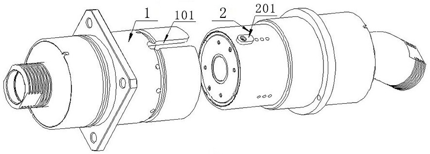
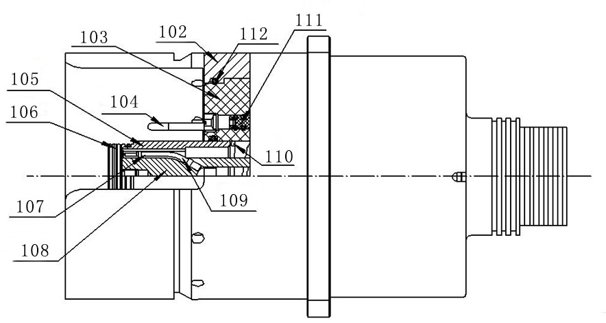
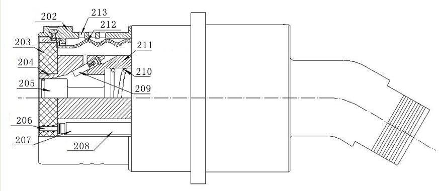

Image

  • A photoelectric composite connector
  • A photoelectric composite connector
  • A photoelectric composite connector

Examples


Embodiment Construction

[0027] The present invention will be further described below in conjunction with the accompanying drawings and specific embodiments. In the description of the present invention, it should be noted that, unless otherwise specified, the meaning of "multiple" is two or more; The orientation or positional relationship indicated by "bottom", "left", "right", "inner", "outer", "front end", "rear end", "head", "tail", etc. are based on the drawings The orientation or positional relationship is only for the convenience of describing the present invention and simplifying the description, but does not indicate or imply that the device or element referred to must have a specific orientation, be constructed and operated in a specific orientation, and therefore cannot be construed as limiting the present invention . In addition, the terms "first", "second", "third", etc. are used for descriptive purposes only and should not be construed as indicating or implying relative importance.

[00...


PUM


Abstract

A photoelectric composite connector, comprising a socket body provided with a socket sealing chamber and a plug body provided with a plug sealing chamber, the socket sealing chamber is composed of an inner wall of a movable sleeve, an outer wall of a first optical fiber module support member in the socket, and a first optical fiber module support member in the socket. Surrounded by insulators, the movable sleeve bends the optical pins obliquely protruding from the first optical fiber module support to be arranged axially along the socket body, and a movable column and an obliquely arranged jack are arranged in the plug sealing cavity. During the process, the first optical fiber module support pushes the movable column into the plug sealing chamber, the movable sleeve slides into the socket body relative to the first optical fiber module support, the elastic tube restores the tilting device, and the optical pin is arranged in the elastic tube, thereby realizing The optical pin is inserted into the optical jack. The invention has good sealing performance, can realize the underwater plugging and unplugging of the connector, prevents external liquid from entering into the chamber of the connector during the underwater plugging and unplugging process, and ensures the cleanliness of the optical contacts during the underwater plugging and unplugging process.

Description

technical field [0001] The invention relates to the technical field of underwater connectors, in particular to a photoelectric composite connector. Background technique [0002] With the continuous deepening of people's exploration of the marine environment, it is often necessary to carry out a large number of underwater environment operations such as underwater construction or underwater scientific research, and different working modules need to transmit power and signals through connectors. However, if the connector is plugged and unplugged underwater, the external liquid is easy to enter the cavity of the connector, and the optical fiber contact is very sensitive to pollution, which will affect the transmission of optical signals after being polluted by external liquid. In application, the connector is often taken out above the liquid level for plugging and unplugging connection, the operation is complicated and the cost is high. Contents of the invention [0003] The ...

Claims


Application Information

Patent Timeline
Patent Type & Authority Patents(China)
IPC IPC(8): H01R13/52H01R13/523H01R13/629H01R24/00G02B6/38
CPCH01R13/523H01R13/5227H01R13/5219H01R24/00H01R13/629G02B6/3817G02B6/3816G02B6/3869G02B6/3849
Inventor 李思行黄高峰魏丽娟马松阳聂鹏飞徐丽美
Owner CHINA AVIATION OPTICAL-ELECTRICAL TECH CO LTD
Learn More