Filter press with one-way valve compartment type filter plate

A one-way valve and filter press technology, applied in the field of filter press filter plate, can solve problems such as damage, filter cloth damage, filter cloth rubber damage, etc., to improve separation efficiency, improve feeding speed, and secure and reasonable fixing. Effect

Pending Publication Date: 2021-09-24
山东菲特环保设备有限公司
View PDF0 Cites 0 Cited by
  • Summary
  • Abstract
  • Description
  • Claims
  • Application Information

AI Technical Summary

Problems solved by technology

In the process of using a filter press for filtration and separation, it often occurs that the filtrate flows back during the extrusion process and enters the feed pipe. The filtrate flows back and the filtering effect is low, which affects the production progress. The harmful substances in the coal products are not separated completely, resulting in Large pollutants are produced during use, causing environmental pollution and damage, harming human health, and do not meet my country's environmental protection emission standards
[0003] When the internal outlet of the filter press is finished feeding, because the inside of the filter press is filled with filter material, a negative pressure of 0.5-1MPa will be generated, and the filter material inside the filter press will return to the feeding pipe. The action will produce a huge suction force on the filter cloth rubber corresponding to the discharge port, resulting in serious damage to the filter cloth rubber
The existing technology is to thicken the diaphragm at the corresponding position or add steel sheets inside the diaphragm, but a large amount of mud will be pressed back into the feed pipe during pressing, and the deformation of the diaphragm will cause damage to the thickened part of the diaphragm. Cloth is also often damaged

Method used


Image

  • Filter press with one-way valve compartment type filter plate
  • Filter press with one-way valve compartment type filter plate
  • Filter press with one-way valve compartment type filter plate

Examples


Embodiment Construction

[0029] The present invention will be further described below in conjunction with the accompanying drawings and embodiments.

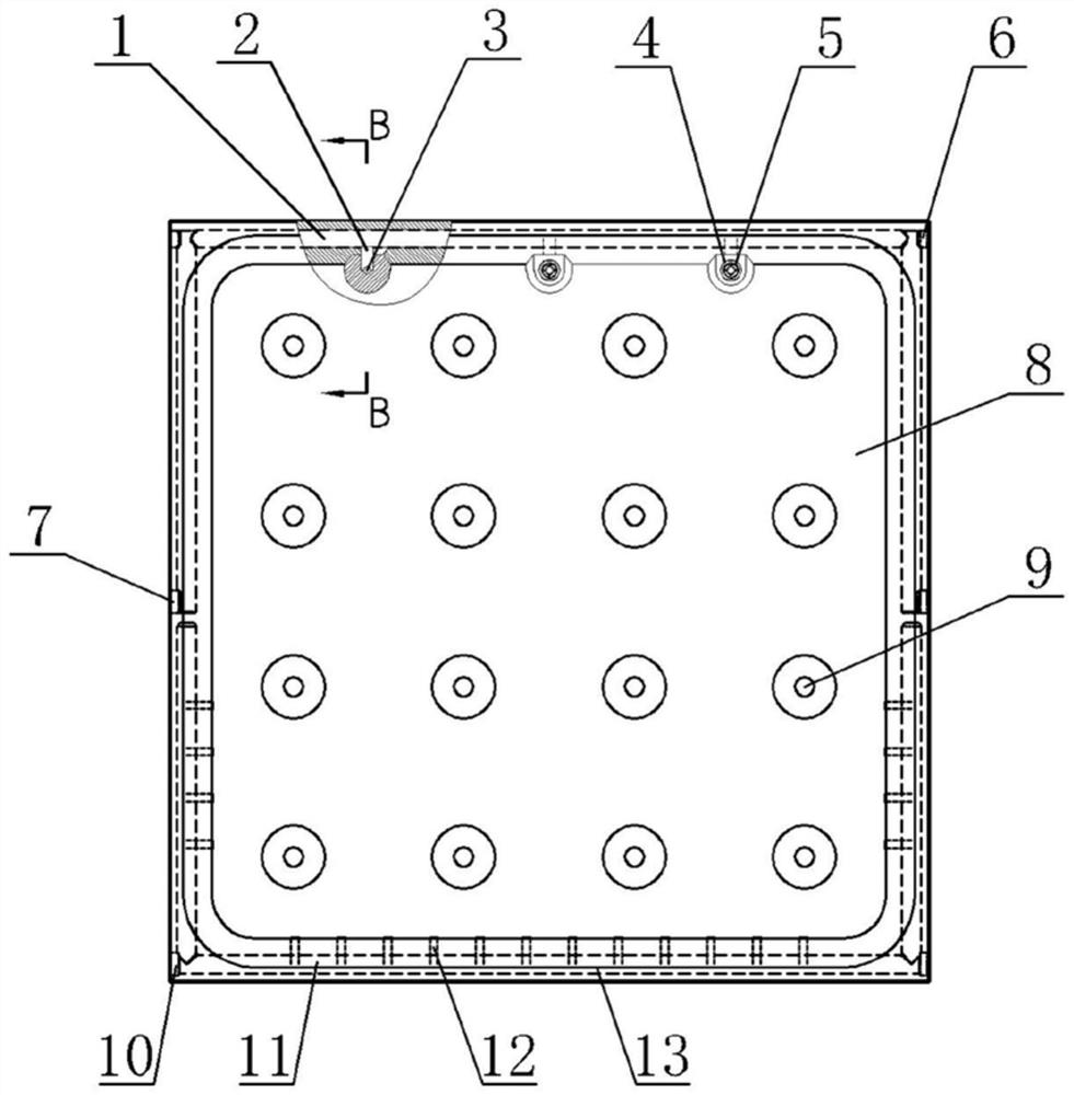
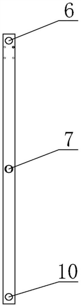
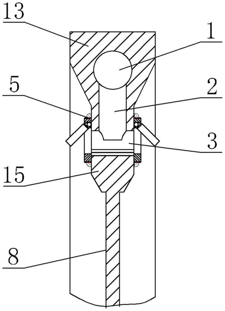
[0030] like Figure 1-6 As shown, a schematic diagram of the overall structure of the one-way valve box filter plate of the present invention is provided. The shown one-way valve box filter plate includes a filter plate 8 and a filter plate frame 13, and the filter plate frame 13 is arranged on the filter plate 8, the thickness of the filter plate frame 13 is greater than the thickness of the filter plate 8, and the filter plate 8 is arranged at the center of the filter plate frame 13. A feeding channel is opened in the filter plate frame 13 of the upper half segment, and a first feeding channel 1 is opened in the vertical filter plate frame 13 of the upper half segment and the upper end, horizontal filter plate frame 13, The lower end of the first feeding channel 1 at the upper end is provided with a single or a plurality of evenly arranged second fee...


PUM


Abstract

The invention discloses a filter press with a one-way valve compartment type filter plate, which comprises a filter plate and a filter plate frame, wherein the filter plate frame is arranged at the edge of the filter plate. The filter press is characterized in that a feeding channel is arranged in the filter plate frame of the upper half section and used for conveying a filter material, a discharging port is formed in the inner side of the filter plate frame and used for discharging the filter material, a feeding port is formed in the outer side of the filter plate frame, and the feeding port and the discharging port are communicated with the interior of the feeding channel; a one-way valve is arranged on the frame of the filter plate at the discharging port and is used for preventing the filter material from flowing back into the feeding channel; a water outlet pipeline is arranged in the filter plate frame of the lower half section, a plurality of filtered water inlets which are uniformly arranged are formed in the inner side of the filter plate frame and are used for infiltration of filtered water, and the filtered water inlets are communicated with the interior of the water outlet pipeline; and a water outlet is formed in the bottom of the filter plate frame and used for outflow of filtered water. By arranging the one-way valve, the filter material is effectively prevented from flowing back into the feeding channel.

Description

technical field [0001] The invention relates to a filter plate of a filter press, more specifically, to a filter press with a one-way valve box filter plate. Background technique [0002] In the current mineral processing industry, such as the production and smelting of coal washing plants, it is often necessary to separate solid-liquid mixtures of various solid-liquid mixtures. The separation equipment currently used is mainly filter presses. In the process of using a filter press for filtration and separation, it often occurs that the filtrate flows back during the extrusion process and enters the feed pipe. The filtrate flows back and the filtering effect is low, which affects the production progress. The harmful substances in the coal products are not separated completely, resulting in Larger pollutants are produced during use, causing environmental pollution and damage, harming human health, and do not meet my country's environmental protection emission standards. [00...

Claims


Application Information

Patent Timeline
IPC IPC(8): B01D25/12B01D25/30
CPCB01D25/302B01D25/305
Inventor 林海燕沈玺王振伟
Owner 山东菲特环保设备有限公司
Why Eureka
Try Eureka