An assembly and method suitable for batch electron beam welding of sputter rings

An electron beam welding and vacuum electron beam welding technology, which is applied in the field of magnetron sputtering, can solve the problems of low efficiency of vacuum electron beam welding, etc., and achieves the advantages of saving multiple vacuuming and cooling time, convenient and flexible combination, and improving production efficiency. Effect

Active Publication Date: 2022-07-19
GRIKIN ADVANCED MATERIALS
View PDF7 Cites 0 Cited by
  • Summary
  • Abstract
  • Description
  • Claims
  • Application Information

AI Technical Summary

Problems solved by technology

The efficiency of vacuum electron beam welding is low. The objective factor is that welding needs to be carried out in a vacuum environment. Vacuuming is required before welding. After the workpiece is welded, the workpiece needs to be cooled. Each welding vacuuming and cooling takes time.

Method used


Image

  • An assembly and method suitable for batch electron beam welding of sputter rings
  • An assembly and method suitable for batch electron beam welding of sputter rings
  • An assembly and method suitable for batch electron beam welding of sputter rings

Examples


Embodiment 1

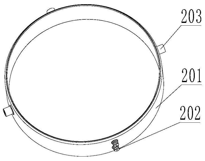
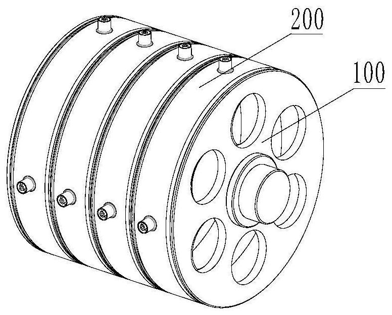
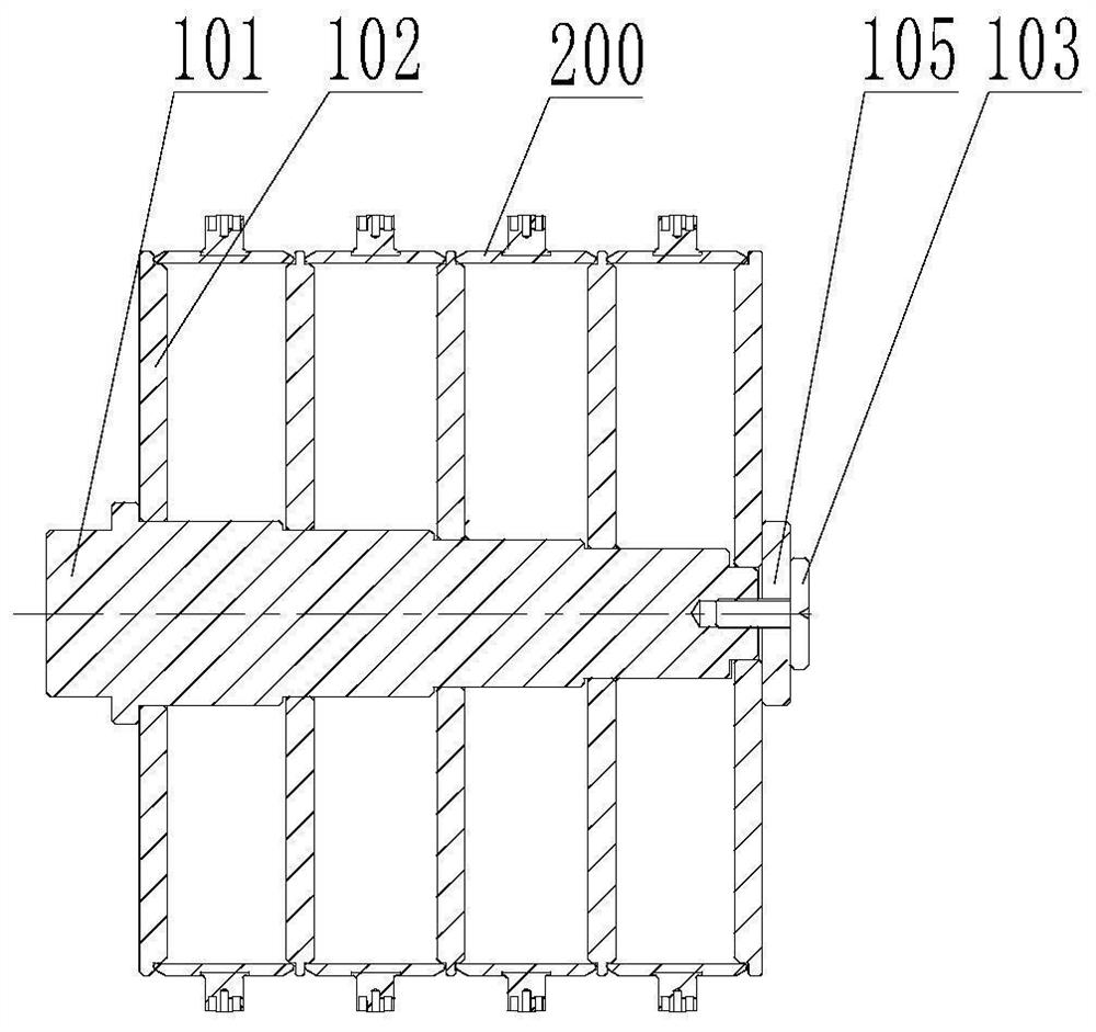
[0030] like image 3 Shown is a schematic diagram of the assembly when welding four sputter rings. After the mandrel 101 is fixed on the chuck of the vacuum electron beam welder and adjusted, a separator 102 is first installed on the mandrel 101, and then the sputtering ring 200 and the separator 102 are installed in sequence, and a total of 4 sputterings are installed Ring 200, separator 102, and finally install the baffle 105 behind the last separator, adjust the relative positions of the supports 203 and electrodes 202 of the four sputtering rings 200 so that the supports 203 of the four sputtering rings 200 are parallel to each other. On the same line of the centerline of the mandrel, the electrodes 202 of the four sputtering rings 200 are located on the same line parallel to the centerline of the mandrel, tighten the bolts 103, and push the top of the vacuum electron beam welding machine table to the bolts 103. , so that the sputter ring batch welding assembly is install...

Embodiment 2

[0032] like Figure 4 Shown is a schematic diagram of the assembly when welding three sputtering rings. After the mandrel 101 is fixed on the vacuum electron beam welding machine chuck and adjusted, a separator 102 is first installed on the mandrel 101, and then the sputtering rings are installed in sequence. The ring 200 and the separator 102 are installed three times in total, and the relative positions of the supports 203 and the electrodes 202 of the three sputter rings 200 are adjusted so that the supports 203 of the three sputter rings 200 are parallel to each other. The electrodes 202 of the three sputtering rings 200 are located on the same line parallel to the centerline of the mandrel, and the first sleeve 104 is placed on the mandrel 101, and finally the baffle 105 is placed on the mandrel 101. After being installed on the first sleeve 104, the bolts 103 are tightened, and the top of the vacuum electron beam welding machine table is pushed onto the bolts 103, so tha...

Embodiment 3

[0034] like Figure 5 Shown is a schematic diagram of the assembly when welding two sputtering rings. After the mandrel 101 is fixed on the vacuum electron beam welding machine chuck and adjusted, a separator 102 is first installed on the mandrel 101, and then the sputtering rings are installed in sequence. The ring 200 and the separator 102 are installed three times in total, and the relative positions of the supports 203 and the electrodes 202 of the two sputter rings 200 are adjusted so that the supports 203 of the two sputter rings 200 are parallel to each other. The electrodes 202 of the two sputtering rings 200 are located on the same line parallel to the centerline of the mandrel, and the second sleeve 106 is placed on the mandrel 101, and finally the baffle 105 After being installed on the second sleeve 106, the bolts 103 are tightened, and the top of the vacuum electron beam welding machine table is pushed onto the bolts 103, so that the sputter ring ring batch weldin...


PUM


Abstract

The invention proposes an assembly and method for batch electron beam welding of sputtering rings, including a mandrel, a partition, a sleeve, a baffle and a bolt. The mandrel is fixed on the chuck of the electron beam welding machine, and the tail can be supported by the tip of the tailstock on the working table of the electron beam welding machine. When welding sputtering rings in batches, multiple sputtering rings can be installed at one time, one sputtering ring is fixed by two spacers, and finally fixed by means of baffles and bolts. During welding, it is only necessary to set parameters such as the first sputtering ring support and electrode coordinates, high pressure, beam current and linear speed, and other sputtering rings can be automatically welded by programming. The sputtering ring batch electron beam welding assembly and method reduces the time for vacuuming and cooling multiple times, and also reduces the time for setting coordinate parameters multiple times, improves the production efficiency, and reduces the production cost of the enterprise.

Description

technical field [0001] The invention belongs to the technical field of magnetron sputtering, in particular to a batch electron beam welding assembly and method suitable for sputtering rings. Background technique [0002] Magnetron sputtering is a thin film deposition technology commonly used in the production process of modern semiconductor chips. It uses high-energy particles to bombard a target with high purity, so that the atoms of the target escape from the surface and are uniformly deposited on the substrate to form a uniform The barrier layer, interconnection line and contact layer of the integrated circuit are formed on the substrate after grinding and polishing processes. In the cavity of the magnetron sputtering machine, the sputtering ring is a component that is used together with the corresponding target and is placed between the target and the substrate. The movement of material atoms is restrained, so that the incident angle of the coating is more vertically co...

Claims


Application Information

Patent Timeline
Patent Type & Authority Patents(China)
IPC IPC(8): B23K15/06B23K37/04
CPCB23K15/06B23K37/0435
Inventor 张延宾张晓娜宋泽鹏李嘉郭凤岐丁照崇冯昭伟李武林邱明亮
Owner GRIKIN ADVANCED MATERIALS
Why Eureka
Try Eureka