Supercharge Your Innovation With Domain-Expert AI Agents!

Czochralski single crystal charging method

A single crystal and charging technology, which is applied in the directions of single crystal growth, single crystal growth, and polycrystalline material growth, etc., can solve problems such as furnace accidents, reduced service life and safety, and longer time for feeding materials, so as to avoid Accidents, rapid chemical accidents, and the effect of reducing heat loss

Inactive Publication Date: 2021-09-24
宁夏协鑫晶体科技发展有限公司
View PDF5 Cites 0 Cited by
  • Summary
  • Abstract
  • Description
  • Claims
  • Application Information

AI Technical Summary

Problems solved by technology

The current method is to increase the chemical power of the heater and supply more heat to achieve the purpose of accelerating the chemical speed. However, due to the limitations of the heater material itself and the supporting power supply cabinet and other equipment, the heater power can only be increased to 100- 150KW, the higher the power of the heater, the lower the service life and the safety of use. Once the abnormality of heating and breaking occurs during the materialization process, it will cause a furnace accident
In addition, the top of the current crucible is an open structure without heat preservation, and the heat is easily lost, and argon gas easily enters the gap between the raw materials in the crucible and takes away the heat in the crucible, resulting in a longer time for the materialization

Method used


Image

  • Czochralski single crystal charging method
  • Czochralski single crystal charging method
  • Czochralski single crystal charging method

Examples


Embodiment Construction

[0023] The present invention can be better understood from the following examples.

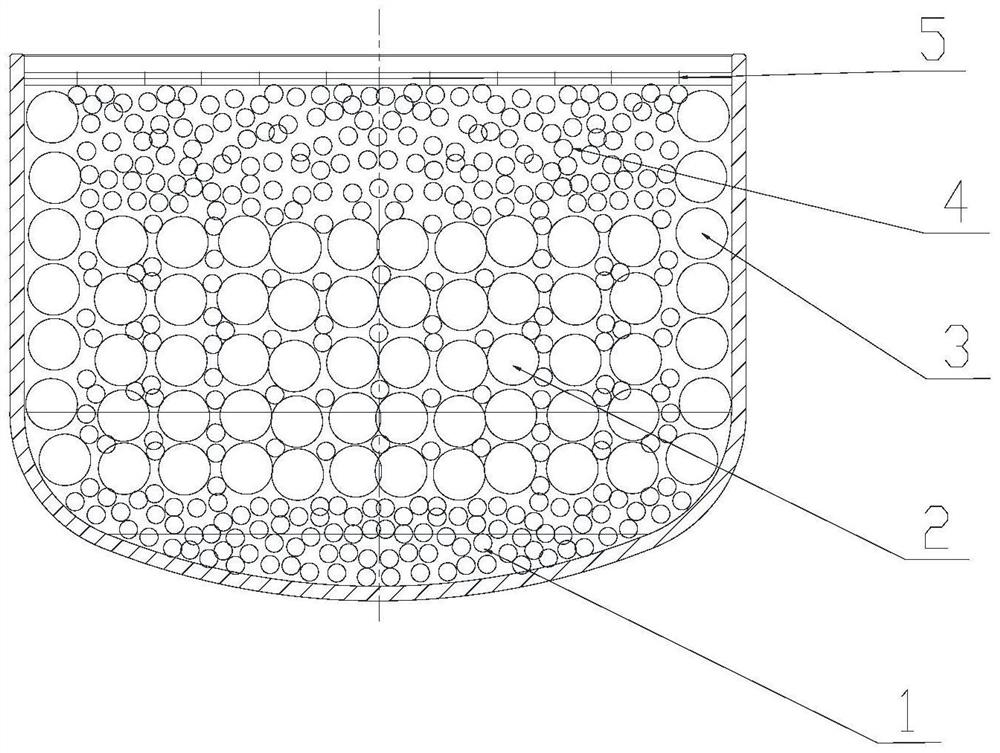
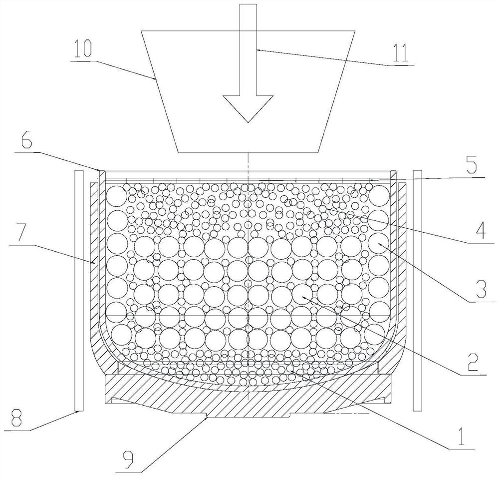
[0024] Such as figure 1 As shown, the Czochralski single crystal charging process of the present invention performs regional configuration of silicon materials of different shapes, and the specific steps are as follows:

[0025] First, fill small material at the bottom of the quartz crucible to form a small material bottom layer 1 with a thickness of 80-120 mm.

[0026] Subsequently, on the top of the small material bottom layer 1, the large material is stacked successively, and when each layer of large material is stacked, the gap of the large material is filled with the small material to form the composite layer 2 of the large and small material. When stacking the composite layer 2 of large and small materials, pay attention to the contact between the periphery of the composite layer 2 of large and small materials and the inner wall of the crucible, and use large materials to be stacked clo...


PUM

PropertyMeasurementUnit
thicknessaaaaaaaaaa
diameteraaaaaaaaaa
thicknessaaaaaaaaaa

Abstract

The invention discloses a Czochralski single crystal charging method which comprises the following steps: firstly, filling small materials at the bottom of a quartz crucible to form a small material bottom layer with the thickness of 80-120mm; sequentially stacking large materials on the upper part of the small material bottom layer, and filling gaps of the large materials with the small materials until 2 / 3 of the height of the crucible is filled when each layer of large materials is stacked, so as to form a large and small material composite layer; then, paving a large material on the periphery of the upper portion of the large and small material composite layer and tightly attached to the inner wall of the crucible to form a large material enclosure layer, and meanwhile, filling the middle of the large material enclosure layer with the small material to form a small material filling layer till the small material filling layer is 50-60 mm away from the top of the quartz crucible; and finally, paving more than two layers of sheet-shaped raw materials on the upper parts of the large material enclosure layer and the small material filling layer to form a sheet-shaped material covering layer. According to the Czochralski single crystal charging method disclosed by the invention, the purposes of quickly melting materials and avoiding accidents are achieved by adopting regional raw material configuration. Sheet-shaped silicon materials are introduced to block the top of the crucible to reduce heat loss, low-temperature argon is prevented from entering gaps of the silicon materials to take away heat, and the material melting speed is increased.

Description

technical field [0001] The invention relates to the field of single crystal silicon production, in particular to a Czochralski single crystal charging method. Background technique [0002] With the continuous development of the photovoltaic industry, large thermal field and large feeding volume have become the development trend of the industry. Due to the continuous increase of feeding volume, the time of materialization is also increasing. Speeding up the speed of materialization can effectively reduce the time of materialization during crystal pulling. The proportion of time, improve production efficiency. The current method is to increase the chemical power of the heater and supply more heat to achieve the purpose of accelerating the chemical speed. However, due to the limitations of the heater material itself and the supporting power supply cabinet and other equipment, the heater power can only be increased to 100- 150KW, the higher the power of the heater, the longer i...

Claims


Application Information

Patent Timeline
Patent Type & Authority Applications(China)
IPC IPC(8): C30B29/06C30B15/02
CPCC30B29/06C30B15/02
Inventor 郑伟扬
Owner 宁夏协鑫晶体科技发展有限公司
Features
  • R&D
  • Intellectual Property
  • Life Sciences
  • Materials
  • Tech Scout
  • Unparalleled Data Quality
  • Higher Quality Content
  • 60% Fewer Hallucinations
Learn More