High-resistance-coefficient resistance alloy wire smelting device
An alloy wire and high-resistance technology, which is applied in the field of high resistivity resistance alloy wire smelting devices, can solve problems such as difficult equipment cleaning and increased production costs, and achieve the effects of ensuring processing quality, saving production costs, and avoiding environmental pollution
- Summary
- Abstract
- Description
- Claims
- Application Information
AI Technical Summary
Problems solved by technology
Method used
Image

Examples
Embodiment 1
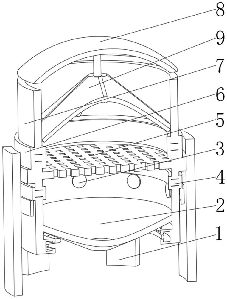
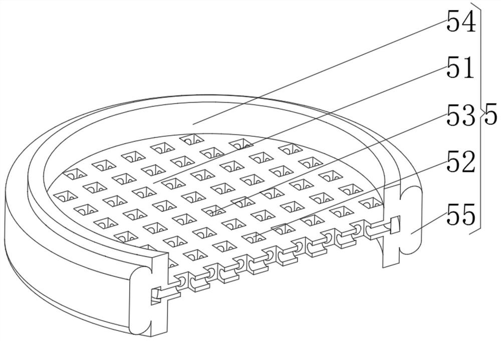
[0037] see figure 1 , 2, 4. The present invention provides a technical solution: a high resistivity resistance alloy wire smelting device, specifically comprising:
[0038] A support frame 1, the support frame 1 has an arc plate main body, and a collection device 2 installed on the inner surface of the arc plate main body, and an annular open flame furnace 3 installed on the top of the collection device 2, and a lower assembly installed on the top of the annular open flame furnace 3 device 4, and the smelting device 5 installed on the top of the lower assembly device 4, and the upper assembly device 6 installed on the top of the smelting device 5, and the feed cylinder 7 installed on the top of the upper assembly device 6, and the top of the feed cylinder 7 The movable end cover 8, and the auxiliary feeding device 9 installed in the middle of the bottom of the movable end cover 8, through the overall segmented design, it is convenient to disassemble and clean each part, and a...
Embodiment 2
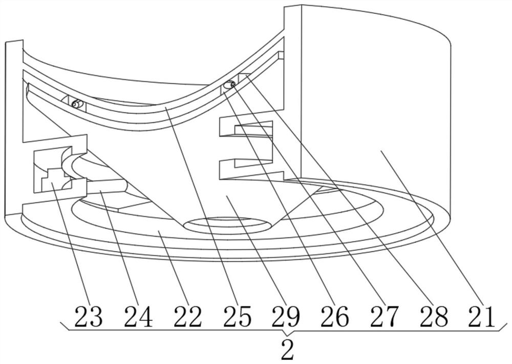
[0048] see Figure 1-4 On the basis of Embodiment 1, the present invention provides a technical solution: the collection device 2 includes:
[0049] Protective cylinder 21, the protective cylinder 21 has a ring-shaped main body, and a concave track 22 installed at the bottom of the inner surface of the ring-shaped main body, and a motion motor 23 installed inside the concave track 22, and a friction motor installed on the side of the motion motor 23 away from the ring-shaped main body rod 24;
[0050] Collector plate 25, the collector plate 25 has a cone main body, and the concave ring rail 26 installed on the bottom of the collector plate 25, and the ball 27 installed on the top of the concave ring rail 26, and the top of the ball ball 27 The upper concave ring rail 28, and the friction plate 29 installed on the upper concave ring rail 28 bottom. Through the circular rotation of the friction rod 24, the friction force is used to frictionally push the friction plate 29, so t...
Embodiment 3
[0054] see Figure 1-5 , On the basis of Embodiment 1 and Embodiment 2, the present invention provides a technical solution: the auxiliary feeding device 9 includes:
[0055] Mounting rod 91, the mounting rod 91 has a columnar body, and a ball head 92 installed at the bottom of the column body, a bar 93 installed on the outer surface of the ball head 92, and an elastic plate 94 installed on the outer surface of the bar 93 , and open a vacuum chamber 95 in the middle of the elastic plate 94 . Through the design of the vacuum chamber 95 of the elastic plate 94, the whole component can buffer the raw materials to be fed, and at the same time realize the self-protection of the component, and at the same time, the assembly of the umbrella-shaped column 93 and the elastic plate 94 can guide the waste gas intensively, It is convenient for centralized collection and purification.
[0056] During use, when the smelt raw material falls, the elastic plate 94 carries and guides the smel...
PUM
 Abstract
Description
Claims
Application Information
 - R&D
- Intellectual Property
- Life Sciences
- Materials
- Tech Scout
- Unparalleled Data Quality
- Higher Quality Content
- 60% Fewer Hallucinations
Browse by: Latest US Patents, China's latest patents, Technical Efficacy Thesaurus, Application Domain, Technology Topic, Popular Technical Reports.
© 2025 PatSnap. All rights reserved.Legal|Privacy policy|Modern Slavery Act Transparency Statement|Sitemap|About US| Contact US: help@patsnap.com