A device and method for stabilizing optical power based on double depolarized beam splitters

A stable control device and depolarized light-splitting technology, which is applied to steering induction equipment and other directions, can solve the problems of accuracy easily affected by temperature and small size, and achieve the effects of improving the stability of detection optical power, improving measurement accuracy and convenient operation.

Active Publication Date: 2022-05-17
BEIHANG UNIV
View PDF0 Cites 0 Cited by
  • Summary
  • Abstract
  • Description
  • Claims
  • Application Information

AI Technical Summary

Problems solved by technology

[0004] The technical problem to be solved by the present invention is: to overcome the deficiency that the existing liquid crystal optical power stabilization method can only effectively and stably control the optical power in the feedback loop, and the control accuracy of the optical power outside the loop is easily affected by temperature, and proposes a method based on double depolarization splitting The high-precision optical power stabilization control device of the prism, under the premise of ensuring a small size of the optical path, suppresses the error of the spectroscopic device caused by the fluctuation of the ambient temperature, significantly improves the stability of the optical power detected outside the ring, and realizes high-precision SERF atomic spin inertial measurement

Method used


Image

  • A device and method for stabilizing optical power based on double depolarized beam splitters
  • A device and method for stabilizing optical power based on double depolarized beam splitters
  • A device and method for stabilizing optical power based on double depolarized beam splitters

Examples


Embodiment Construction

[0019] The present invention will be further described below in conjunction with the accompanying drawings and specific embodiments.

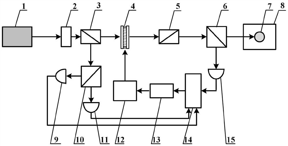
[0020] figure 1 It is a structural block diagram of the implementation of the high-precision optical power stabilization control device based on the double depolarization beam splitter of the present invention. As can be seen from the figure, the present invention includes detection laser 1; 1 / 2 wave plate 2; first Glan Taylor prism 3; liquid crystal phase retarder 4; second Glan Taylor prism 5; Chamber 7; magnetic shielding tube 8; first photodetector 9; second depolarizing beamsplitter prism 10; second photodetector 11; electric control system 12; reference voltage 13;

[0021] First, adjust the optical path so that the detection light emitted by the detection laser is divided into two beams by the 1 / 2 wave plate and the first Glan Taylor prism, and the transmitted light enters the detection light power stabilization module through the liqui...


PUM


Abstract

The invention discloses a high-precision optical power stabilization control device and method based on double depolarization beam splitters. First, the laser output from the laser is divided into two beams, one of which is used as the input of a liquid crystal optical power stabilization control module, and the other beam The laser light is incident on a splitting ratio monitoring module consisting of an auxiliary depolarizing beamsplitter prism (NPBS) and two photodetectors. The splitting ratio monitoring module monitors the fluctuation of the splitting ratio in real time, and inputs the fluctuation signal to the electronic control unit of the optical power control system. The electronic control unit calculates the control voltage of the optical power attenuator according to the fluctuation of the splitting ratio and the feedback optical power signal, so as to realize the environment Out-of-loop detection optical power stabilization control under temperature fluctuations. The present invention only needs to add an auxiliary NPBS to the original optical path to realize the suppression of the splitting ratio fluctuation error of the optical splitting device, and further improve the stability of the detection optical power of the incident air chamber outside the ring on the basis of maintaining the miniaturization of the optical path, and improve the SERF inertial measurement precision.

Description

technical field [0001] The invention relates to the technical field of laser power stabilization control, in particular to a high-precision optical power stabilization control device and method based on double depolarization beam splitting prisms, which can be used in the detection system of SERF atomic spin inertial measurement, and suppress the light splitting caused by environmental temperature changes The fluctuation error of the splitting ratio of the device improves the stability of the detected optical power of the incident atomic gas chamber outside the ring, and reduces the drift of the output signal of the SERF atomic spin inertial measurement system. Background technique [0002] With the development of quantum technology, the use of atomic spin for inertial measurement is one of the important development directions in the future, and the theoretical accuracy of the SERF atomic spin inertial measurement system can reach 10 -8 ° / h, but there is a large gap between ...

Claims


Application Information

Patent Timeline
Patent Type & Authority Patents(China)
IPC IPC(8): G01C19/58
CPCG01C19/58
Inventor 全伟张伟佳段利红范文峰范时秒
Owner BEIHANG UNIV
Why Eureka
Try Eureka