Integrated railway signal relay life test device and method

A railway signal and relay technology, applied in the field of integrated railway signal relay life test device, can solve the problems of not being able to meet the test requirements well, prone to errors, complicated operation, etc., so as to achieve strong anti-interference ability of the device and safe and reliable work. , the effect of simplifying the test procedure

Active Publication Date: 2019-02-05
STANDARDS & METROLOGY RES INST CHINA ACADEMY OF RAILWAY SCI +1
View PDF11 Cites 2 Cited by
  • Summary
  • Abstract
  • Description
  • Claims
  • Application Information

AI Technical Summary

Problems solved by technology

[0016] 2. Long life test cycle
[0017] 3. Different action methods
[0018] 4. The voltage and current requirements of the contacts are different, and the contacts pass through a large current
[0030] 1. The 555timer has poor anti-interference performance and has high requirements for the surrounding electromagnetic compatibility environment. It is very susceptible to interference and causes random changes in the period and duty cycle of the square wave.
[0031] 2. The 555timer has a narrow input voltage range and is easily damaged when the voltage fluctuates, making it difficult for existing devices to work continuously and normally
[0032] 3. The accuracy of frequency adjustment of existing devices depends on the accuracy of capacitance and resistance, and the value of capacitance and resistance purchased on the market cannot accurately meet the test requirements
These differences are gradually amplified during the long-term test, resulting in a large difference between the number of life tests and the actual number
[0033] 4. Each set of existing devices can only conduct life tests on one type of relay
Complex, time-consuming, and error-prone operations in repetitive processes
The whole system has a low degree of integration and cannot well meet the test requirements

Method used


Image

  • Integrated railway signal relay life test device and method
  • Integrated railway signal relay life test device and method
  • Integrated railway signal relay life test device and method

Examples


Embodiment 1

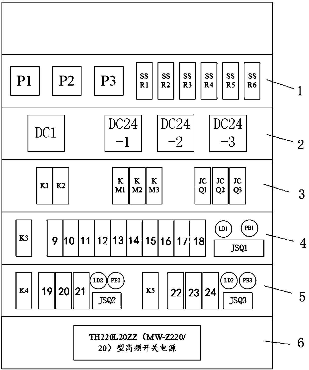
[0080] Example 1: Figure 2 (a), Figure 2 (b), image 3 , Figure 4 , Figure 5 , Image 6 , Figure 7 , Figure 8 and Picture 9 As shown, an integrated railway signal relay life test device is divided into control circuit equipment and load circuit equipment. The control circuit equipment makes the sample relay operate at the specified frequency, and the load circuit equipment applies the standard required voltage and current to the sample relay contact. .

[0081] Control circuit equipment includes:

[0082] (1) Control working layer 1: The first single-chip microcomputer P1, the second single-chip P2, and the third single-chip P3 form a single-chip control group. The models of the first single-chip P1, the second single-chip P2 and the third single-chip P3: PIC18F45K80 are responsible for controlling the sample relay The ratio of operating frequency and on-off time.

[0083] The first single-chip P1, the second single-chip P2, and the third single-chip P3 enter 4-segment codes, ...

Embodiment 2

[0108] Example 2: As shown in Figure 2(a) and Figure 2(b), an integrated railway signal relay life test device is divided into control circuit equipment and load circuit equipment. The control circuit equipment makes the sample relay follow the specified frequency Action, the load circuit equipment applies the voltage and current required by the standard to the sample relay contacts.

[0109] The control circuit equipment includes a control working layer 1, a power supply layer 2, a switch layer 3, a mechanical life test layer 4, an electrical life test layer 5, and a load power supply layer 6. The load circuit equipment includes a load resistance layer 7 and a fan layer 8.

[0110] The electrical life test layer 5 includes the first electrical life test layer (left side) and the electrical life test second layer (right side).

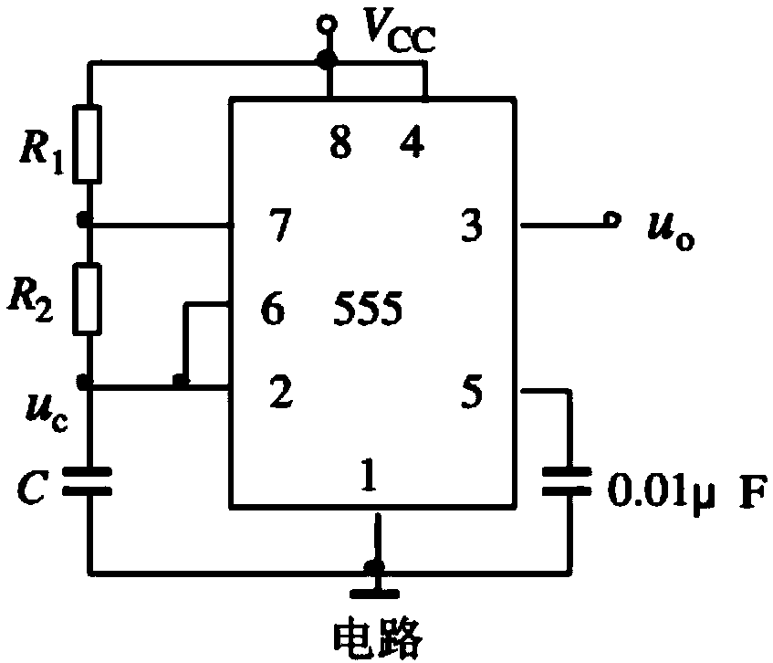
[0111] Such as image 3 As shown, the circuit breaker K2 is connected to AC220V city power and DC1 5V direct current. The first single-chip microcomputer P1 ...

Embodiment 3

[0125] Embodiment 3: An integrated railway signal relay life test method, including the following steps;

[0126] Step 1. Mechanical life test layer:

[0127] Switch on the main circuit breaker K2 of the control circuit equipment, and the first power module DC1 converts AC220V city power into DC5V direct current, which is used as the working power supply of the first single-chip microcomputer P1. According to the sample relay model, use the code selection switch to select the corresponding frequency mode, the first single-chip microcomputer P1 outputs the level signal of the corresponding frequency to the first solid state relay SSR1 coil. The second power supply module DC24-1 outputs DC24V, which is connected to the sample relay coil of the mechanical life test layer through the first solid state relay SSR1 contact, so that the sample relay operates at the specified frequency.

[0128] Step 2. The first layer of the electrical life test of the electrical life test layer 5:

[0129] ...


PUM


Abstract

The invention discloses an integrated railway signal relay life test device, and belongs to the technical fields of traffic information engineering and control-type product detection. The device includes control circuit equipment and load circuit equipment. The control circuit equipment includes a control working layer, a power supply layer, a switch layer, a mechanical life test layer, an electrical life test layer and a load power supply layer. The load circuit equipment includes a load resistance layer and a fan layer. The electrical life test layer includes an electrical life test first-layer and an electrical life test second-layer. According to the device, an equipment utilization rate is high, and an occupied area is small; an effect of using a set of equipment to meet life test requirements of all types of relays is realized; sample relays are plug-and-play, operations are simple and convenient, and an error rate is reduced; anti-interference ability of the device is high, stability is high, and a guarantee is provided for reliability of life tests; and an equipment integration degree is high, a circuit design is clear, overhauling and maintenance of operators are facilitated.

Description

Technical field [0001] The invention relates to an integrated railway signal relay life test device and method, and belongs to the technical field of traffic information engineering and control product detection. Background technique [0002] Railway signal relay is one of the most important and widely used components in the railway safety control system. It is the basic component of the railway department to ensure driving safety. It is widely used in the core code of the existing normal-speed railway relay signal system and the current high-speed railway. Interface, information collection and logical representation of key system equipment. As the key equipment of the signal system to ensure railway transportation safety and improve transportation efficiency, railway signal relays must emphasize "safety", which is mainly reflected in: [0003] 1. The action must be reliable and accurate; [0004] 2. Long service life; [0005] 3. There is sufficient ability to close and open circui...

Claims


Application Information

Patent Timeline
Patent Type & Authority Applications(China)
IPC IPC(8): G01R31/327
CPCG01R31/327
Inventor 何宇晖陈海康王俊飞郑璟瑜马研李小帅刘世鹏付建华
Owner STANDARDS & METROLOGY RES INST CHINA ACADEMY OF RAILWAY SCI
Why Eureka
Try Eureka