
Heavy oil well sand prevention effect evaluation test device and evaluation test method

A technology for testing devices and oil wells, applied in measurement devices, analysis of suspensions and porous materials, instruments, etc., can solve the problems of not reflecting the process of forming sand bridges, poor reproducibility of experimental results, deviation of experimental results, etc., to achieve the experimental period Short, low manufacturing cost, and the effect of reducing experimental bias

Active Publication Date: 2021-09-24
PETROCHINA CO LTD
View PDF8 Cites 0 Cited by
  • Summary
  • Abstract
  • Description
  • Claims
  • Application Information

AI Technical Summary

Problems solved by technology

The simulated sand is an experimental sand prepared by using sand particles of different particle sizes according to the particle size distribution of the formation sand. This preparation method is prone to uneven sand mixing during dry mixing, resulting in large deviations in experimental results.
During the experiment, the problem of poor reproducibility of the experimental results due to uneven sand mixing often occurs
Moreover, due to the need to simulate the production conditions of oil wells and the use of high-pressure pumps and other equipment, currently only simulated sand can be pre-filled and liquid injected for experiments, which cannot reflect the process of formation of sand bridges when formation sand contacts screens or gravel layers, resulting in There is a certain deviation between the experimental results and the actual situation

Method used


Image

  • Heavy oil well sand prevention effect evaluation test device and evaluation test method
  • Heavy oil well sand prevention effect evaluation test device and evaluation test method
  • Heavy oil well sand prevention effect evaluation test device and evaluation test method

Examples


Embodiment Construction

[0032] In order to have a clearer understanding of the technical features, purposes and effects of the present invention, the specific implementation manners of the present invention will now be described with reference to the accompanying drawings.

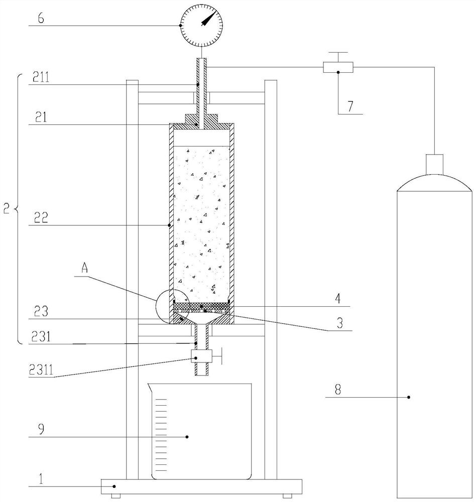
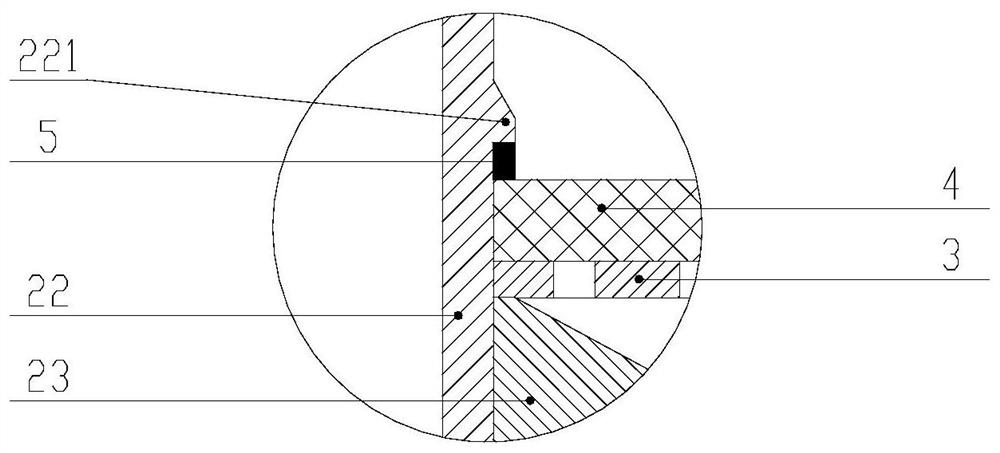
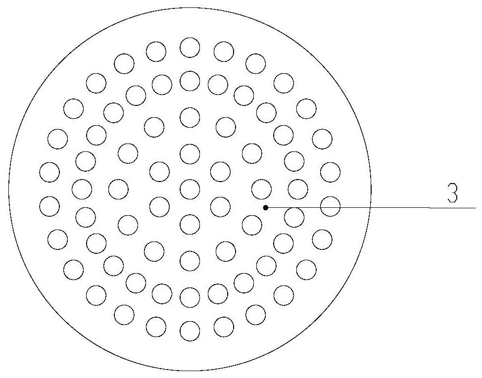
[0033] Such as figure 1 , figure 2 and image 3 As shown, this embodiment provides a sand control effect evaluation test device for heavy oil wells, including a vertically arranged test cylinder 2 with a chamber, the upper end of the test cylinder 2 is connected with a gas source capable of delivering gas to the chamber of the test cylinder 2 8. A support plate 3 with a plurality of through holes is horizontally provided adjacent to the bottom of the chamber, a certain gap is left between the support plate 3 and the bottom surface of the chamber, and a sieve filter sample 4 is provided above the support plate 3. The chamber and above the screen filter sample 4 are filled with uniformly mixed simulated mortar. The lower end su...


PUM


Abstract

The invention relates to a heavy oil well sand prevention effect evaluation test device and evaluation test method. The evaluation test device comprises a vertically arranged test cylinder, the upper end of the test cylinder is connected with a gas source, a support plate is horizontally arranged adjacent to the bottom of a chamber, and a certain gap is reserved between the support plate and the bottom surface of the chamber. A screen pipe filtering sample piece is arranged above the supporting plate, and the portion, located above the screen pipe filtering sample piece, in the cavity is filled with evenly-mixed simulation mortar. A liquid outlet communicated with a space formed by the gap is formed in the lower end face of the testing cylinder, a taper hole with the diameter gradually reduced downwards and communicated with the liquid outlet is formed in the inner wall of the lower end of the testing cylinder, a drain valve is arranged at the liquid outlet, the cross sectional area of the liquid outlet is larger than the overflowing area of the screen pipe filtering sample piece, and a measuring cylinder is arranged below the testing cylinder. The device is low in manufacturing cost, short in experimental period and capable of simulating the process that sand grains form a sand bridge on the surface of the screen pipe, the sand prevention principle is closer to the actual situation, and the test result is more accurate.

Description

technical field [0001] The invention relates to the technical field of oil and gas well exploitation, in particular to a sand control effect evaluation test device and an evaluation test method for heavy oil wells. Background technique [0002] Due to the loose formation and high viscosity of crude oil in heavy oil wells, sand production is common in the production process. In order to ensure the normal mining of sand wells, it is necessary to adopt supporting sand control measures. Screen sand control technology (that is, using only screen for sand control) and gravel packing sand control technology (that is, using both screen and gravel layer for sand control) are the two most widely used sand control technologies at present. Selecting the appropriate sand control screen and gravel size and optimizing the design of the sand control process are the prerequisites for ensuring the sand control effect. [0003] At present, the selection of sand control screens and the design...

Claims


Application Information

Patent Timeline
Patent Type & Authority Applications(China)
IPC IPC(8): G01N15/08
CPCG01N15/08G01N15/0826
Inventor 匡韶华王宝权张建军张洪宝吕民陈磊佟姗姗严蕾岳志强田富
Owner PETROCHINA CO LTD
Learn More