
Double-waveguide/multi-waveguide channel structure working in W wave band and TR module

A channel structure, double waveguide technology, applied in the direction of waveguide, waveguide-type devices, radio wave measurement system, etc., can solve the problems of difficult waveguide structure, complex internal structure, difficulty, etc., to solve the problem of air tightness and avoid mutual interference , taking into account the effect of air tightness

Active Publication Date: 2021-09-24
CHENGDU THUNDER MICROCRYSTALLINE TECH CO LTD
View PDF13 Cites 0 Cited by
  • Summary
  • Abstract
  • Description
  • Claims
  • Application Information

AI Technical Summary

Problems solved by technology

Among them, due to the high frequency of the W-band, the waveguide is generally used as the interface form of the millimeter wave signal, and the waveguide is a conventional interface form, usually in the form of an opening, which has no protective effect on the internal bare chip and other devices.
At present, most of the existing airtight solutions for waveguide ports solve the airtight problem of a single waveguide channel.
However, it is very difficult to realize the airtightness of the multi-channel waveguide interface, especially for the highly integrated TR module
The second difficulty is that since the waveguide output interfaces of the multi-channel TR module are often arranged in parallel, its internal structure is complex; limited by the processing means, it cannot be processed and formed in one piece, and it must be divided structurally, and then screwed to lock
However, there are two problems with this structure: one is that due to the use of this structure, there must be a waveguide gap between the waveguide channels, and the waveguide gap will cause mutual interference between the channels, so how to solve the mutual interference between the waveguide channels is a problem. Second, the structure does not have airtight characteristics, so how to achieve airtightness for the divided waveguide structure is also a major difficulty
The third difficulty is that TR modules, especially high-power TR modules, have many internal devices, involving circulators, microstrip lines, millimeter-wave chips, digital chips, power chips, connectors, PCB boards, etc. devices, and the number is large, so how to achieve a hermetic package while ensuring a certain degree of integration is very difficult

Method used


Image

  • Double-waveguide/multi-waveguide channel structure working in W wave band and TR module
  • Double-waveguide/multi-waveguide channel structure working in W wave band and TR module
  • Double-waveguide/multi-waveguide channel structure working in W wave band and TR module

Examples


Embodiment 2

[0041] The present embodiment discloses a work W in a multi-band wave guide channel structure.

[0042] Speaking of the foregoing, multi-channel waveguide structure can be extended based on the above-described dual channel waveguide structure. like Image 6 Shows a schematic structural diagram of a four-channel expansion, is expanded more channels, the same token can be extended. For multi-channel waveguide structure, preferably, each of the adjacent output waveguide channels between the convex structure 11 or 13 are enclosed in the same shape, e.g. a rectangle are, of course, does not exclude the possibility of the convex structure 13 enclosed shape different, or even circumference shape is not necessarily limited to be the same to a rectangle. And, each projection direction of the projection of the same structure, so on the industrial production and processing, the same, not that different projection directions of the raised structures intended effect can not be achieved, the emb...

Embodiment 3

[0044] like Figure 7 Shown as a circuit configuration diagram of a multi-channel waveguide module TR W-band work in the hermetically sealed package, the channel module 1 × 8, W-band millimeter-wave transmission signal from the common waveguide interfaces - interfaces 1a- input waveguide is entered, after 1 divided into two 2-way power divider, two driving TR chip are input, then the access points 1 4-way power splitter 4 into two sub-1 power splitter 4 has eight outputs. Each channel signal input chip vector modulation, phase-shifting the signal attenuation in the vector modulator chip, chip output vector modulation stage TR connected to the end of the chip amplification, the amplified signal is sent after the final amplifier power amplifier chip; finally, the power the amplified signal into the loop, and then outputs the access channel waveguide (i.e. waveguide output interface). For the millimeter wave reception signal path and the transmit signal path Instead, only the receptio...


PUM


Abstract

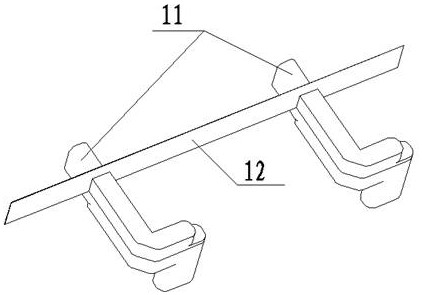
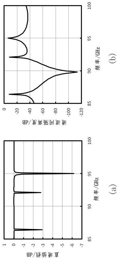
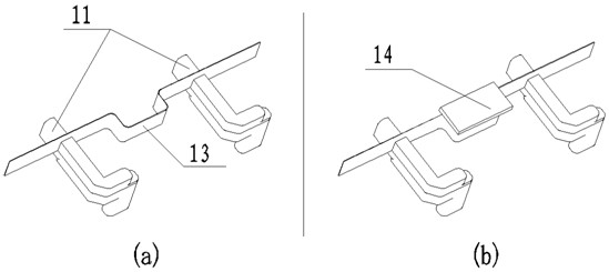
The invention discloses a double-waveguide / multi-waveguide channel structure working in a W wave band and a TR module. A waveguide gap between adjacent output waveguide channels protrudes in the normal direction perpendicular to the waveguide gap in a bending mode to form a protruding structure, a protruding decoupling strand is covered with a wave absorbing material, the double-waveguide channel structure is obtained, and the multi-waveguide channel structure is obtained through similar expansion. The multi-waveguide channel TR module is provided with a module main cavity, a first side and a second side with openings are designed on opposite surfaces of the module main cavity, the first side is sealed by an upper airtight cover plate, a waveguide cover plate and a radio frequency power supply plate are mounted in the first side, a circulator and a power supply sub-plate are mounted in the second side, the circulator is sealed by a lower airtight cover plate, a power supply sub-plate cover plate covers the outer side of the power supply sub-plate, and a power supply insulator passes through the module main cavity to connect the power supply sub-plate and the radio frequency power supply plate. According to the invention, mutual interference between channels can be effectively avoided under the W wave band, and effective airtightness of the module can be realized.

Description

Technical field [0001] The present invention relates to millimeter wave communications and radar, and in particular a disturbance in the working channels W between the anti-dual band waveguide channel structure in one of the working channels W between the anti-multi-band interference wave guide channel structure, and one of the working in the W-band waveguide channels hermetically sealed multi-TR module. Background technique [0002] W-band electronic information device because of its small size, light weight, high resolution and wide bandwidth and other inherent advantages, both in military and civil field has great potential. W-band technology can be used in communications, millimeter-wave radar, the airport object detection, millimeter wave security and other fields in recent years has attracted huge investment in research. Wherein, TR module as an important component of the W-band electronic system, at the rear end of the antenna, from the main amplified signal attenuation an...

Claims


Application Information

Patent Timeline
IPC IPC(8): H01P5/16H01P3/00H04B1/40H04B15/00G01S7/02
CPCH01P5/16H01P3/00H04B1/40H04B15/00G01S7/02
Inventor 冯琳丁卓富唐耀宗徐明昊
Owner CHENGDU THUNDER MICROCRYSTALLINE TECH CO LTD
Learn More