
High-efficiency straw header

A high-efficiency, header technology, used in headers, harvesters, agricultural machinery and implements, etc., can solve problems such as low adaptability, low conveying efficiency, and corn and grain accumulation and blockage, and improve the delivery efficiency and conveying efficiency. The effect of high and high cutting efficiency

Pending Publication Date: 2021-09-28
河北英虎农业机械股份有限公司
View PDF2 Cites 2 Cited by
  • Summary
  • Abstract
  • Description
  • Claims
  • Application Information

AI Technical Summary

Problems solved by technology

[0003] For example, the existing patent ZL201120170919.7 discloses a corn harvester's ear-picking head, including a stem-cutting head, which uses the cutting knife at the front end of the stem-cutting head to cut off the corn grains, but this cutting knife is fixed. Yes, only use its thrust to cut off the corn grain, this cutting method is easy to cause missed cutting of the corn grain
Moreover, it uses a belt conveyor to transport the corn grain backwards. This belt conveyor has low conveying efficiency, and it is easy to cause the accumulation and blockage of the corn grain, resulting in equipment failure.
[0004] In addition, the existing patent ZL201310064409.7 discloses a small and medium-sized self-propelled stem and ear corn combine harvester. After feeding to the feeding device, although it has a certain ability to feed backwards, the feeding ability of the auger blades is limited, and its feeding efficiency is difficult to meet the needs of fast harvesting
Further, the height of the auger is fixed, which increases the difficulty of installation, and cannot be adjusted in height, and cannot adapt to corn harvesting of different densities, and has low adaptability

Method used


Image

  • High-efficiency straw header
  • High-efficiency straw header
  • High-efficiency straw header

Examples


Embodiment Construction

[0035] Exemplary embodiments of the present disclosure will be described in more detail below with reference to the accompanying drawings. Although exemplary embodiments of the present disclosure are shown in the drawings, it should be understood that the present disclosure may be embodied in various forms and should not be limited to the embodiments set forth herein. Rather, these embodiments are provided so that the present disclosure can be more thoroughly understood and the scope of the present disclosure can be fully conveyed to those skilled in the art.

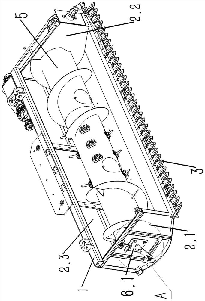
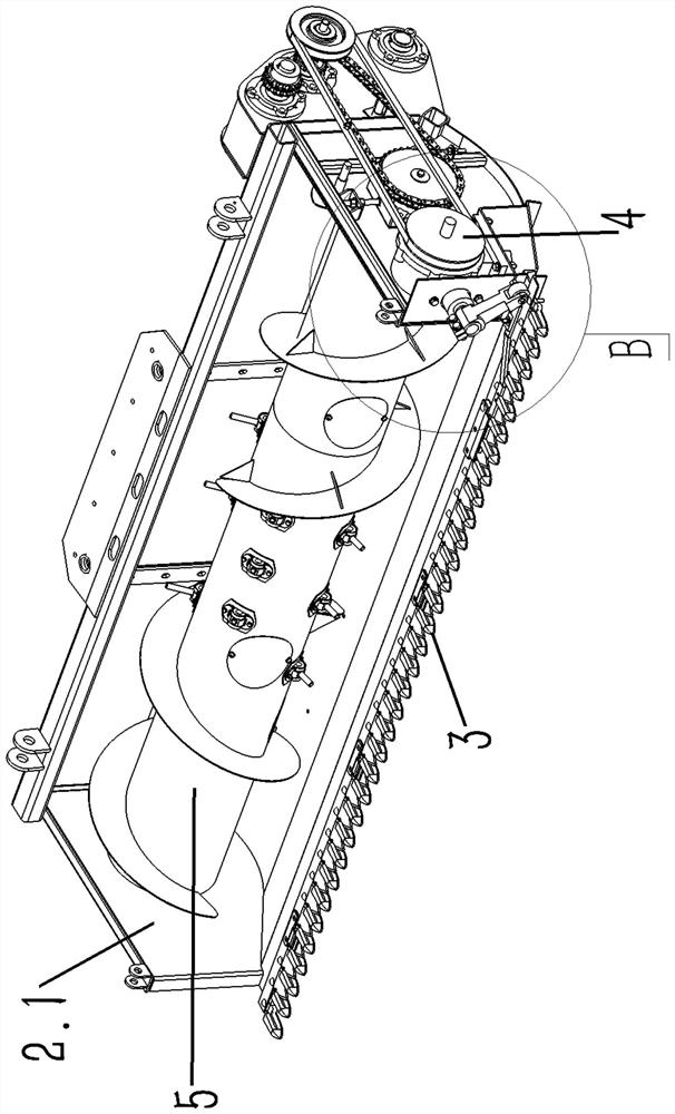
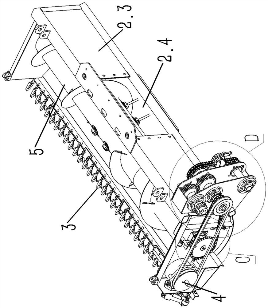
[0036] Such as Figure 1-3 As shown, according to the embodiment of the present invention, a high-efficiency straw header is proposed, including a header frame 1 and a header shell installed on the header frame 1, and the header shell includes a left side plate 2.1, Right side panel 2.2, two rear side panels 2.3 and bottom panel. A straw output port 2.4 is formed between the two rear side panels 2.3. The front end of...


PUM


Abstract

The invention discloses a high-efficiency straw header which comprises a header frame and a header shell installed on the header frame, wherein the header shell comprises a left side plate, a right side plate, two rear side plates and a bottom plate, a straw output port is formed between the two rear side plates, a straw cutting knife mechanism is arranged at the front end of the bottom plate, the straw cutting knife mechanism comprises a fixed knife assembly and a movable knife assembly, the fixed knife assembly comprises fixed knives arranged in parallel, each fixed knife comprises two fixed knife blocks, a fixed knife groove is formed between the fixed knife blocks, one ends of the two fixed knife blocks are connected together through a fixed knife installation block, the fixed knife installation blocks are installed on a fixed knife connection angle plate, and the fixed knife connection angle plate is installed at the front end of the bottom plate. According to the high-efficiency straw header, a reciprocating type cutting knife mechanism is adopted, a straw auger is provided with symmetrical spiral blades, a stirring and conveying mechanism is arranged in the middle of the straw auger, the height of the straw auger is adjustable, and the high-efficiency straw header is high in cutting efficiency, conveying efficiency and adaptability.

Description

technical field [0001] The invention relates to a high-efficiency straw harvesting platform, which belongs to the technical field of corn harvesting. Background technique [0002] The corn harvester is a kind of agricultural machinery for ear harvesting and stalk harvesting. It cuts off the corn grain through the straw header in the header device, and sends it back to the feeding device and crushing device for processing. The straw harvesting unit generally cuts the corn grain from the bottom by the cutter set at the front end, and then moves the corn grain backward to the feeding device and crushing device at the rear end of the harvesting unit through the straw auger. Therefore, the efficiency of the cutter and the delivery efficiency of the straw auger have a significant impact on the harvesting of corn stalks. [0003] For example, the existing patent ZL201120170919.7 discloses a corn harvester's ear-picking head, including a stem-cutting head, which uses the cutting kn...

Claims


Application Information

Patent Timeline
Patent Type & Authority Applications(China)
IPC IPC(8): A01D47/00A01D69/06A01D57/00A01D45/02
CPCA01D47/00A01D69/06A01D57/00A01D45/02
Inventor 李衡李侠杨香林
Owner 河北英虎农业机械股份有限公司
Learn More