Slender Z-shaped part composite forming device and forming method

A compound forming and parts technology, which is applied in the field of compound forming devices for slender Z-shaped parts, can solve the problems of large calibration workload, difficult part molding, and large springback of parts, so as to achieve small processing volume, not easily deformed, and improve The effect of forming efficiency

Active Publication Date: 2021-09-28
CHENGDU AIRCRAFT INDUSTRY GROUP
View PDF18 Cites 2 Cited by
  • Summary
  • Abstract
  • Description
  • Claims
  • Application Information

AI Technical Summary

Problems solved by technology

[0009] In order to solve the above-mentioned technical problems, the present invention proposes a compound forming device and forming method for slender Z-shaped parts, which can effectively solve the problem of low forming efficiency, especially the large springback of the part after the part is formed with sag on the side, and the part is not easy to be molded and corrected. workload problem

Method used


Image

  • Slender Z-shaped part composite forming device and forming method
  • Slender Z-shaped part composite forming device and forming method
  • Slender Z-shaped part composite forming device and forming method

Examples


Embodiment 1

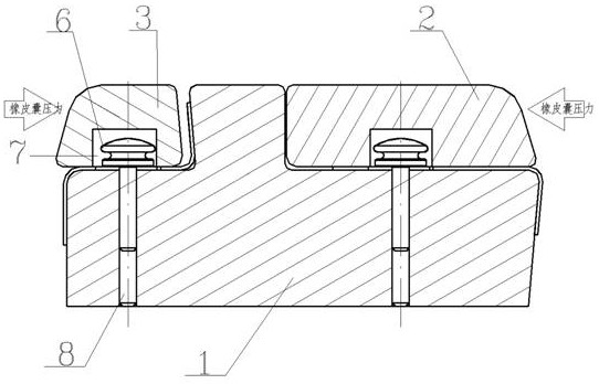
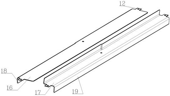
[0050] As a basic embodiment of the present invention, the present invention includes a compound forming device for elongated Z-shaped parts, including a mold body I 1 , a cover plate 2 and a mold body II 3 . The mold body I 1 is in the shape of a "convex" and forms working surfaces for the process A 16 and process B 17 respectively. The width of the working surface in the process A 16 is greater than the width of the working surface in the process B 17 , and the width of the working surface in the process B 17 matches the width of the web surface of the Z-shaped part 5 . The inner shape of the working surface in step B17 matches the outer shape of the working surface in step A16, and the outer shape of the working surface in step B17 and the outer shape of the working surface in step A16 can be the same or different. Steps 4 matching the sunken area on the side of the Z-shaped part 5 are provided on the working surfaces of the process A 16 and the process B 17 . The Z-shaped...

Embodiment 2

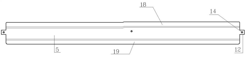
[0054] As the best embodiment of the present invention, the present invention includes a compound forming device for elongated Z-shaped parts, and the formed Z-shaped part 5 includes a flange A 18, a flange B 19 and a web. Refer to the attached Figure 10 , This forming device includes a mold body I1, a cover plate 2 and a mold body II 3, for the convenience of operation, the two ends of the mold body I 1 are provided with suspension rings 10, and the cover plate 2 is provided with a handle 11.

[0055] Refer to the attached Figure 5 , the mold body I 1 is in the shape of a "convex" and forms working surfaces for the process A 16 and the process B 17 respectively. Refer to the attached Figure 7 , the distance between the working surfaces of the process A 16 and the process B 17 needs to consider the unfolded shape of the part process B 17, and the value of L is generally 20-100 mm. The width of the working surface in the process B 17 matches the width of the web surface o...

Embodiment 3

[0062] As another preferred embodiment of the present invention, the present invention includes a composite forming method for elongated Z-shaped parts, comprising the following steps:

[0063] ⅰ. Design the first positioning hole 14 and the process lug 12 on the Z-shaped part 5 according to the three-dimensional digital model, and determine the expanded profile of the Z-shaped part 5, blanking and making the first positioning hole 14 according to the expanded profile;

[0064] ⅱ. Formed parts:

[0065] Process A 16: Position the Z-shaped part 5 on the mold body I 1 with the positioning pin 6, position the cover plate 2 with the counter-mold pin 8 and place it on the Z-shaped part 5, and use a rubber bladder hydraulic press to form the bent edge A of the sunken side 18;

[0066] Process B 17: Remove the Z-shaped part 5 formed in process 1, then rotate the Z-shaped part 5 by 180°, use the positioning pin 6 to position the Z-shaped part 5 on the mold body I 1, and use the mold ...


PUM


Abstract

The invention relates to the technical field of airplane sheet metal part manufacturing, in particular to a slender Z-shaped part composite forming device and forming method. The forming device comprises a die body I, a cover plate and a die body II; the die body I is in an inverted T shape and forms working faces used for the procedure A and the procedure B respectively; the width of the working face of the procedure B is matched with that of the web face of the Z-shaped part, and the shape of the inner side of the working face of the procedure B is matched with that of the outer side of the working face of the procedure A; steps are arranged on the working surfaces; the cover plate and the die body II are all molded surfaces, positioning pin avoiding grooves and die matching pin holes are formed in the cover plate and the die body II, and the die matching pin holes in the die body II are oblong holes; and the forming method comprises the steps that under the action of a rubber bag forming machine, the die body II is pressed towards the die body I, and the bent edge A is formed while the bent edge B is formed. By means of the forming device and the forming method, the problems that the forming efficiency is low, and particularly after the side face of the part is sunken and formed, the part is large in springback, the part is not prone to being attached to a die, and the correction workload is large can be effectively solved.

Description

technical field [0001] The invention relates to the technical field of manufacturing aircraft sheet metal parts, in particular to a compound forming device and a forming method for elongated Z-shaped parts. Background technique [0002] At present, the known aircraft Z-shaped parts are the supporting components of the skin parts that constitute the aerodynamic shape. Due to the needs of the aircraft's aerodynamic shape and functional layout, some Z-shaped parts are in the shape of a single curved surface, some are in the shape of a hyperboloid, and some are in the shape of an open or closed angle. , and there are complex shapes with one or more depressions. The surface accuracy of Z-shaped parts affects aircraft assembly, strength, surface quality, etc. How to produce Z-shaped parts with high quality and high efficiency is one of the important symbols to measure a country's aircraft manufacturing capability. Such parts generally use rubber bags to make the plate into a Z s...

Claims


Application Information

Patent Timeline
Patent Type & Authority Applications(China)
IPC IPC(8): B21D5/04B21D5/00B21D1/00B21D53/88
CPCB21D5/04B21D5/002B21D1/00B21D53/88
Inventor 王军曾德标王高明谭书论
Owner CHENGDU AIRCRAFT INDUSTRY GROUP
Why Eureka
Try Eureka