
Welding mechanism and welding equipment with same

A welding mechanism and welding metal technology, applied in welding equipment, non-electric welding equipment, metal processing equipment, etc., can solve the problems of labor and affect production efficiency, and achieve the effect of reducing volume, saving time, and speeding up production efficiency

Pending Publication Date: 2021-09-28
东莞市大为工业科技有限公司
View PDF0 Cites 0 Cited by
  • Summary
  • Abstract
  • Description
  • Claims
  • Application Information

AI Technical Summary

Problems solved by technology

[0003] Existing diffusion welding devices usually include a vacuum chamber and a pressurized welding mechanism installed in the vacuum chamber. During the welding process, it is necessary to place the metal parts to be welded in the vacuum chamber first, then close the vacuum chamber door, and then pressurize The welding mechanism presses the metal parts to be welded tightly, and finally the air in the vacuum chamber is drawn out to weld the metal parts to be welded; since the control of the pressure welding mechanism and the opening and closing of the vacuum chamber need to be controlled manually, it is easy to affect the production efficiency

Method used


Image

  • Welding mechanism and welding equipment with same
  • Welding mechanism and welding equipment with same
  • Welding mechanism and welding equipment with same

Examples


Embodiment Construction

[0036] Embodiments of the present application are described in detail below, examples of which are shown in the drawings, wherein the same or similar reference numerals denote the same or similar elements or elements having the same or similar functions throughout. The embodiments described below by referring to the figures are exemplary, and are only for explaining the present application, and should not be construed as limiting the present application.

[0037] In the description of the present application, it should be understood that the orientation descriptions, such as the orientation or positional relationship indicated by up, down, front, rear, etc., are based on the orientation or positional relationship shown in the drawings, and are only for the convenience of describing this application. The application and simplified description do not indicate or imply that the device or element referred to must have a specific orientation, be constructed and operate in a specific...


PUM


Abstract

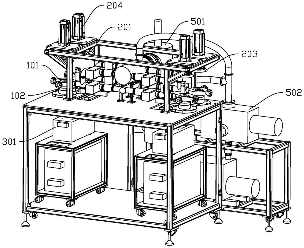
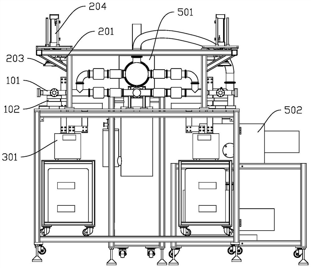
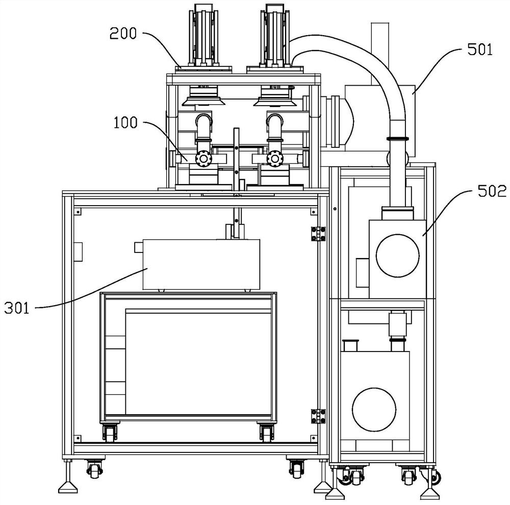
The invention discloses a welding mechanism and welding equipment with the same. The welding mechanism comprises a first sealing assembly and a second sealing assembly; the first sealing assembly is used for containing a to-be-welded metal piece; the second sealing assembly and the first sealing assembly can move relatively; an adsorption part is arranged between the first sealing assembly and the second sealing assembly, and the first sealing assembly and the second sealing assembly are connected in a sealed mode through the adsorption part so that a vacuum chamber can be formed between the first sealing assembly and the second sealing assembly; and the second sealing assembly is further used for pressing the to-be-welded metal piece. According to the technical scheme, the to-be-welded metal piece can be pressed while the vacuum chamber is formed, and therefore the production efficiency can be improved.

Description

technical field [0001] The present application relates to the field of welding technology, in particular to a welding mechanism and welding equipment having the same. Background technique [0002] Diffusion welding is to press the metal parts to be welded together, and place them in a vacuum or protective atmosphere furnace to heat, so that the microscopic plastic deformation will occur on the small unevenness of the welding surface of the metal parts to be welded, so as to achieve close contact. Among them, the welding method in which atoms diffuse each other to form a metallurgical connection. [0003] Existing diffusion welding devices usually include a vacuum chamber and a pressurized welding mechanism installed in the vacuum chamber. During the welding process, it is necessary to place the metal parts to be welded in the vacuum chamber first, then close the vacuum chamber door, and then pressurize The welding mechanism presses the metal parts to be welded tightly, and ...

Claims


Application Information

Patent Timeline
Patent Type & Authority Applications(China)
IPC IPC(8): B23K20/02B23K20/26
CPCB23K20/026B23K20/26
Inventor 黄欢东张庆鹏黄勇平尤晓镇曾志强林炳鑫叶钦昌黄志东祁嘉永黄小龙
Owner 东莞市大为工业科技有限公司
Learn More