Supercharge Your Innovation With Domain-Expert AI Agents!

Illuminating lamp light source control system

A light source control and lighting technology, applied in optical signals, signal devices, transportation and packaging, etc., can solve the problems of insufficient lighting brightness and inconcentration of light, and achieve high control accuracy, good real-time performance and less delay. Effect

Pending Publication Date: 2021-09-28
佛山市南海区协隆电器有限公司
View PDF0 Cites 0 Cited by
  • Summary
  • Abstract
  • Description
  • Claims
  • Application Information

AI Technical Summary

Problems solved by technology

[0003] However, due to the influence of the brightness of the LED light source, when the high beam is formed, the problems of insufficient lighting brightness and inconcentrated light often occur, especially in bad weather or dark environments, which cannot meet actual needs.

Method used


Image

  • Illuminating lamp light source control system
  • Illuminating lamp light source control system
  • Illuminating lamp light source control system

Examples


Embodiment 1

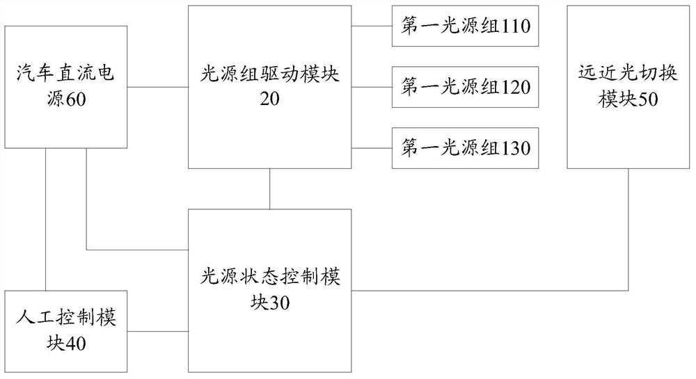
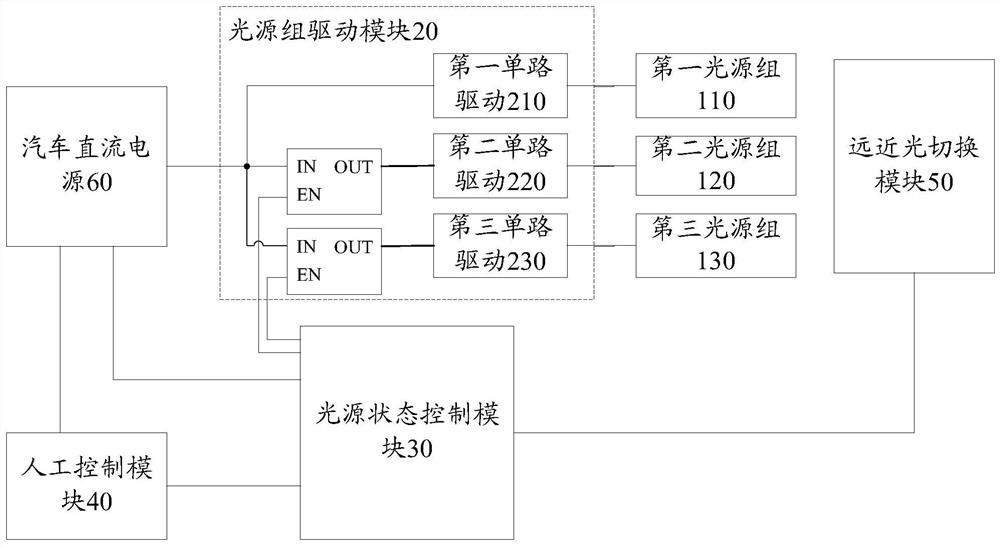
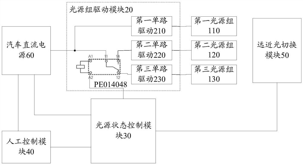
[0027] Such as figure 1 As shown, the present invention provides a lighting source control system, which includes sequentially connected light source groups, a light source group drive module 20, a light source state control module 30, and a manual control module 40, and the light source state control module 30 connected The far and near light switching module 50, the light source group includes the first light source group 110, the second light source group 120 and the third light source group 130; Controlled by the light source group driving module 20, the light source group driving module 20 controls the opening and closing of the first light source group 110, the second light source group 120 and the third light source group 130 to form the required lighting state. Specifically, the first light source group 110, the second light source group 120 and the third light source group 130 respectively include two or more LED light sources, and the light source group driving modul...

Embodiment 2

[0040] Different from Embodiment 1, in this embodiment, the light source state control module 30 includes a first level conversion circuit 330, a buffer The circuit 340 and the second level conversion circuit 350 , as well as the counter 360 and the voltage conversion circuit 370 arranged between the buffer circuit 340 and the light source group driving module 20 and connected in sequence. Specifically, the first level shifting circuit 330 and the second level shifting circuit 350 are used to convert the voltage of the input signal into a target voltage, both have the same structure and the same working principle, taking the first level shifting circuit 330 as an example , which consists of MOS transistors Q1, Q2 and resistors R3, R4, R5, R6. When the gate of MOS transistor Q1 is low level, MOS transistor Q1 is disconnected, the drain of MOS transistor Q1 is high level VCC1, the gate of MOS transistor Q2 is high level VCC1, MOS transistor Q2 is turned on, and the drain of MOS ...


PUM


Abstract

The invention discloses an illuminating lamp light source control system. The system comprises a light source group, a light source group driving module, a light source state control module and a manual control module which are connected in sequence, and a high-beam and low-beam switching module connected with the light source state control module, the light source groups comprise a first light source group, a second light source group and a third light source group; the light source state control module controls the high and low beam switching module and the light source group driving module according to a signal transmitted by the manual control module; and the light source group driving module controls the opening and closing of the first light source group, the second light source group and the third light source group to form a required lighting state. High-beam auxiliary lighting is performed through second light source group or third light source group, so that high-beam center illumination can be improved, and different light source groups can be switched through manual control module, light source state control module and light source group driving module according to lighting requirements of different environments to perform auxiliary lighting. The system is better in adaptability and can meet more complex distance light requirements. The system is simple in operation and good in real-time performance.

Description

technical field [0001] The invention relates to the technical field of lighting control, in particular to a lighting light source control system. Background technique [0002] With the development of semiconductor technology, LED (Light Emitting Diode, light-emitting diode) light source has the advantages of high efficiency, energy saving, environmental protection, low cost and long life, and is gradually replacing traditional incandescent lamps and energy-saving lamps, becoming a general lighting Light source, especially in the headlights of the far and near light has been widely used. [0003] However, due to the influence of the brightness of the LED light source, when the high beam is formed, the problems of insufficient illumination brightness and inconcentrated light often occur, especially in bad weather or dark environments, which cannot meet actual needs. Contents of the invention [0004] Aiming at the problems existing in the prior art, the present invention pr...

Claims


Application Information

Patent Timeline
IPC IPC(8): B60Q1/14
CPCB60Q1/1407B60Q1/1415B60Q1/1446
Inventor 苏运清
Owner 佛山市南海区协隆电器有限公司
Features
  • R&D
  • Intellectual Property
  • Life Sciences
  • Materials
  • Tech Scout
  • Unparalleled Data Quality
  • Higher Quality Content
  • 60% Fewer Hallucinations
Learn More