Pressurizing device for construction based on constructional engineering and using method thereof

A pressurizing device and construction engineering technology, which is applied in the processing of building materials, construction, building construction, etc., can solve the problems of inconvenient motor disassembly and maintenance, elastic bracket loosening and reduced elasticity, motor vibration, etc., and achieve long-term use effect Reliable, easy to disassemble and repair, relieve pressure fluctuation effect

Inactive Publication Date: 2021-09-28
周昊呈
View PDF1 Cites 1 Cited by
  • Summary
  • Abstract
  • Description
  • Claims
  • Application Information

AI Technical Summary

Problems solved by technology

[0006] In order to solve the above-mentioned technical problems, the present invention provides a pressurizing device for construction based on construction engineering and its use method to solve the problem of motor, cooling pipe, and pressurizing pump when the pressurizing device for construction of existing construction engineering is in use. The connection structure of the shell is complicated, which is not convenient for disassembly and maintenance of the motor, and the motor generates vibration during operation, which easily affects the service life of the motor. At the same time, the connecting ring in the coupling is squeezed for a long time, which will cause the elastic bracket to loosen and reduce its elasticity. The deflection of the impeller shaft will cause damage, and in the process of pressurizing the concrete, it is easy to inhale air, resulting in unstable delivery flow and affecting work efficiency.

Method used


Image

  • Pressurizing device for construction based on constructional engineering and using method thereof
  • Pressurizing device for construction based on constructional engineering and using method thereof
  • Pressurizing device for construction based on constructional engineering and using method thereof

Examples


Embodiment

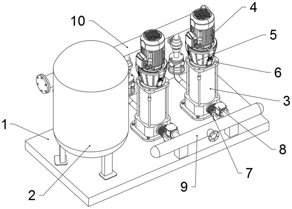
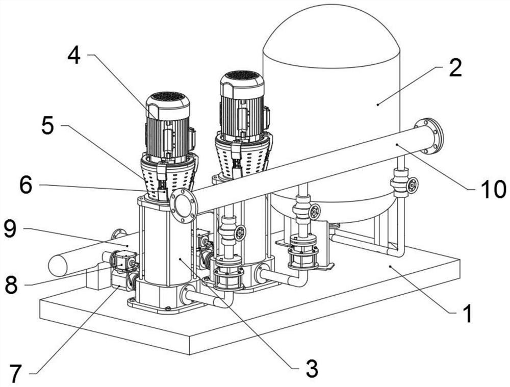
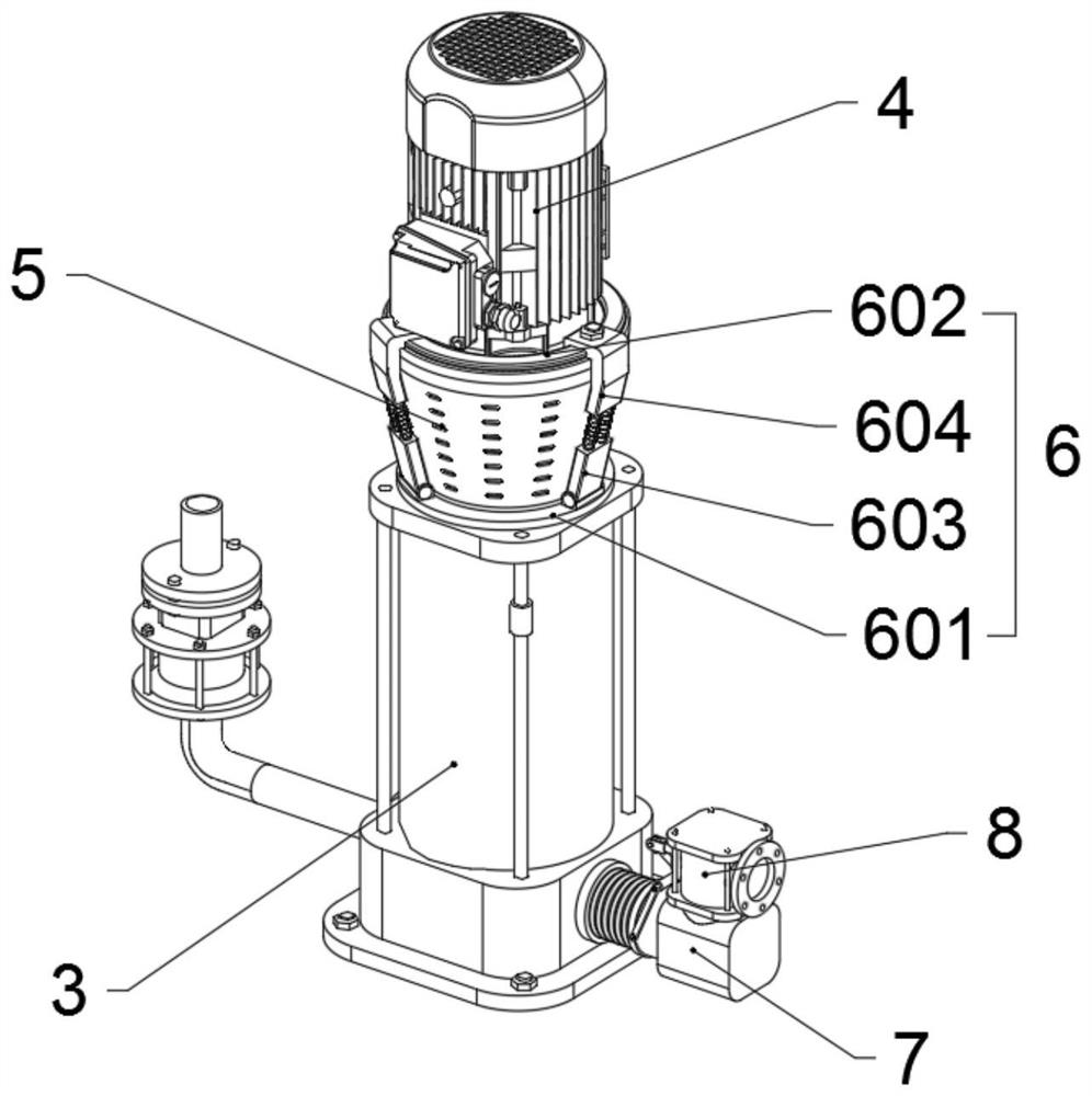
[0044] as attached figure 1 To attach Figure 9 Shown:

[0045] The present invention provides a pressurizing device for construction based on construction engineering and its use method, including a bottom plate 1;

[0046] There is an air pressure tank 2 on the left side of the top of the base plate 1, and two pressurized pump housings 3 are provided on the right side of the top of the base plate 1, and the two pressurized pump housings 3 are vertically distributed in parallel, and the air pressure tank 2 and the pressurized The pump casings 3 are all connected to the output pipe 10 through conduits. The pressurized pump casing 3 includes a shaft 301, a ratchet claw 302 and an impeller 303. The pressurized pump casing 3 is a cylindrical cavity structure, and the pressurized pump A shaft 301 is arranged in the cavity of the housing 3, and the shaft 301 is rotationally connected with the booster pump housing 3 through a bearing, and the shaft 301 is provided with an impeller...


PUM


Abstract

The invention provides a pressurizing device for construction based on constructional engineering and a using method thereof, and relates to the technical field of building construction. The pressurizing device solves the problems that when an existing pressurizing device for construction of constructional engineering is used, the connecting structure of a motor, a heat dissipation pipe and a pressurizing pump shell is complex, the motor is inconvenient to disassemble and maintain, meanwhile, a connecting ring in a coupler is extruded for a long time, so that an elastic support is loosened, the elasticity is reduced, an impeller shaft rod is deflected and damaged, and in the concrete pressurizing process, air is easily sucked in, the conveying flow is unstable, and the working efficiency is influenced. The pressurizing device comprises a bottom plate, wherein the left side of the top end of the bottom plate is provided with an air pressure tank, and the right side is provided with two booster pump shells. According to the pressurizing device, due to the fact that an elastic support is pressed and fixed between a top half coupling and a bottom half coupling, through the elastic effect of a compression spring and the structural characteristics of the elastic support, the elastic support is effectively prevented from being loosened to cause elasticity reduction, and it is guaranteed that the using effect is long and reliable.

Description

technical field [0001] The present invention relates to the technical field of building construction, and more specifically relates to a pressurizing device for construction based on building engineering and a method for using the same. Background technique [0002] The Architectural Engineering major is mainly responsible for the teaching and management of the Architectural Engineering direction of the Civil Engineering major. It mainly cultivates and masters the basic theories and basic knowledge of engineering mechanics, soil mechanics, surveying, building architecture and structural engineering disciplines. It refers to all kinds of buildings and engineering facilities that provide the material and technical basis for human life and production. During the construction of existing high-rise buildings, a pressurizing device is required to transport concrete to a high place during construction, and pressurize to ensure the delivery of concrete, thereby ensuring normal opera...

Claims


Application Information

Patent Timeline
Patent Type & Authority Applications(China)
IPC IPC(8): E04G21/04
CPCE04G21/04
Inventor 周昊呈
Owner 周昊呈
Why Eureka
Try Eureka