
Lifter distributor for tractor

A distributor and lifter technology, which is applied in the lifting device of agricultural machinery, application, agricultural machinery, etc., can solve the problems that the hydraulic system is easily polluted, unfavorable to install oil filtering equipment, and hydraulic components are paralyzed, so as to achieve stable connection and sealing Effect guarantee, the effect of reducing the probability of leakage

Active Publication Date: 2021-09-28
SHANDONG HONGYU AGRI MACHINERY
View PDF14 Cites 2 Cited by
  • Summary
  • Abstract
  • Description
  • Claims
  • Application Information

AI Technical Summary

Problems solved by technology

[0002] As the domestic tractor industry is in line with the world, the global tractor parts procurement boom is taking shape. The hydraulic lifters of large foreign brands of tractors are gradually entering domestic tractor manufacturers, and the main core control element of the lifter is the distributor, which is generally installed on the lifter. The inner cavity or the outer one is placed on the right side of the lifter. Its superior performance determines the working reliability of the hydraulic system. However, due to the harsh working environment of the tractor, it has been working in high temperature, dust, load, corrosion, vibration and other working environments for a long time. , the hydraulic system is easily polluted. If it enters the hydraulic components, it is easy to cause paralysis or even damage to the hydraulic components. Due to the high integration of the tractor lift, it is not conducive to installing oil filtering equipment, which needs to be improved urgently.

Method used


Image

  • Lifter distributor for tractor
  • Lifter distributor for tractor
  • Lifter distributor for tractor

Examples


Embodiment Construction

[0015] In order to make the purpose, technical solutions and advantages of the embodiments of the present invention clearer, the technical solutions in the embodiments of the present invention will be clearly and completely described below in conjunction with the drawings in the embodiments of the present invention. Obviously, the described embodiments It is a part of embodiments of the present invention, but not all embodiments. Based on the embodiments of the present invention, all other embodiments obtained by persons of ordinary skill in the art without creative efforts fall within the protection scope of the present invention.

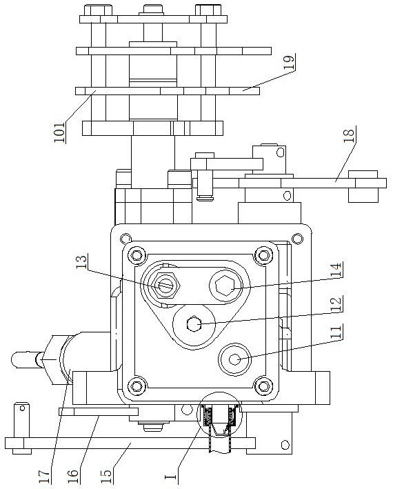
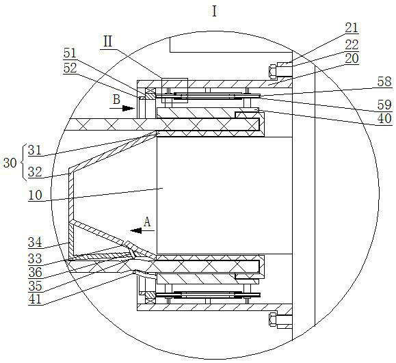
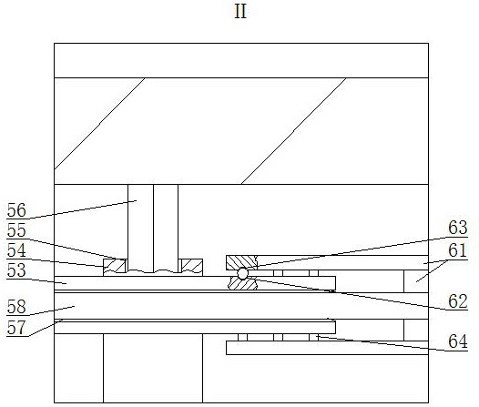
[0016] A lifter distributor for a tractor, as shown in the figure, includes a distributor main body, an oil port 10 is arranged on the distributor main body, a sleeve 20 is arranged outside the oil port 10, the sleeve 20 is connected with the distributor main body, and the oil port 10 and the oil supply pipeline is provided with a filter cup 30, t...


PUM


Abstract

The invention provides a lifter distributor for a tractor, which comprises a distributor body; an oil port is arranged on the distributor body; a sleeve is arranged outside the oil port and connected with the distributor body; a filter cup is arranged between the oil port and an oil supply pipeline and comprises a soft cup edge and an elastic cup body; the cup edge is used for being connected with the oil supply pipeline, and the cup body is used for filtering out impurities in hydraulic oil; and the cup body is of a conical structure, a U-shaped through groove is arranged on the cup body, an impurity storage cover is arranged outside the U-shaped through groove and comprises a plane and an arc-shaped face, and an included angle between the plane and the arc-shaped face is smaller than 90 degrees. According to the lifter distributor for the tractor provided by the invention, stable connection between the oil supply pipeline and the oil port can be achieved, the sealing effect can be guaranteed, the probability of hydraulic oil leakage is reduced, in addition, a hydraulic oil filtering function is achieved at the connecting position, filtered impurities are concentrated into the impurity storage cover, filtering holes of the filtering cup cannot be blocked, repeated use can be achieved, the space occupied by the distributor is not increased, and the distributor is convenient to disassemble and assemble.

Description

technical field [0001] The invention belongs to the field of lifting distributors, in particular to a lifting distributor for tractors. Background technique [0002] As the domestic tractor industry is in line with the world, the global tractor parts procurement boom is taking shape. The hydraulic lifters of foreign big brand tractors are gradually entering domestic tractor manufacturers, and the main core control element of the lifter is the distributor, which is generally installed on the lifter. The inner cavity or the outer one is placed on the right side of the lifter. Its superior performance determines the working reliability of the hydraulic system. However, due to the harsh working environment of the tractor, it has been working in high temperature, dust, load, corrosion, vibration and other working environments for a long time. , The hydraulic system is easily polluted. If it enters the hydraulic components, it is easy to cause paralysis or even damage to the hydra...

Claims


Application Information

Patent Timeline
Patent Type & Authority Applications(China)
IPC IPC(8): F15B13/02F15B21/041A01B63/10
CPCF15B13/02F15B21/041A01B63/10F15B2211/615
Inventor 李松燕
Owner SHANDONG HONGYU AGRI MACHINERY
Learn More