
Reluctance motor with double-layer stator structure

A reluctance motor, stator structure technology, applied in the magnetic circuit shape/pattern/structure, winding conductor shape/pattern/structure, magnetic circuit and other directions, can solve the problem of high motor operating frequency, large core loss, low motor efficiency, etc. problems, to achieve the effect of improving the average torque, less iron loss and less wind resistance

Pending Publication Date: 2021-09-28
HUAZHONG UNIV OF SCI & TECH
View PDF7 Cites 0 Cited by
  • Summary
  • Abstract
  • Description
  • Claims
  • Application Information

AI Technical Summary

Problems solved by technology

[0003] However, when the traditional switched reluctance motor runs at high speed, the efficiency of the motor is low and the heat is high, mainly because the motor operates at high frequency at high speed, which produces a large iron loss; at the same time, the rotor with a salient pole structure will cause a large windage loss.
The shortcomings of high iron consumption and large rotor wind resistance loss have become the technical bottlenecks that limit the development of switched reluctance motors to higher speed and higher power
[0004] Existing switched reluctance motors generally adopt a long magnetic circuit structure, with large core loss, poor torque performance, and low power density

Method used


Image

  • Reluctance motor with double-layer stator structure
  • Reluctance motor with double-layer stator structure
  • Reluctance motor with double-layer stator structure

Examples


Embodiment Construction

[0026] In order to make the object, technical solution and advantages of the present invention clearer, the present invention will be further described in detail below in conjunction with the accompanying drawings and embodiments. It should be understood that the specific embodiments described here are only used to explain the present invention, not to limit the present invention. In addition, the technical features involved in the various embodiments of the present invention described below can be combined with each other as long as they do not constitute a conflict with each other.

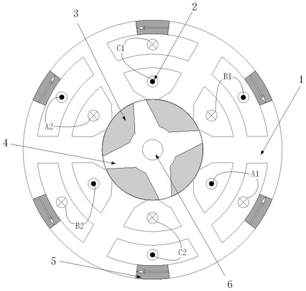
[0027] The invention provides a reluctance motor with a double-layer stator structure, comprising:

[0028] shaft;

[0029] The rotor is arranged on the outside of the rotating shaft, and includes a non-magnetically conductive support and a plurality of rotor segmented cores; the plurality of rotor segmented cores are evenly fixed in the slots of the non-magnetically conductive support;

[003...


PUM


Abstract

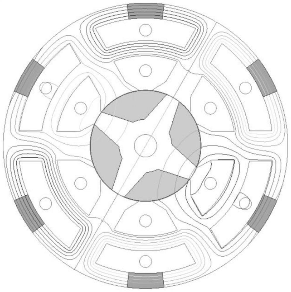
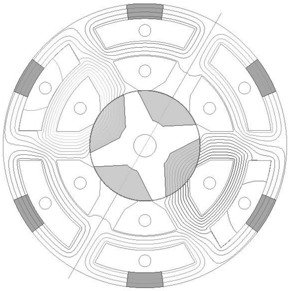
The invention discloses a reluctance motor with a double-layer stator structure, which belongs to the field of motors. The reluctance motor with a double-layer stator structure comprises a rotating shaft, a rotor, a stator and a plurality ofpermanent magnets, wherein the rotor is arranged on the outer side of the rotating shaft and comprises a non-magnetic support and a plurality of rotor block iron cores; the plurality of rotor block iron cores are uniformly fixed in the clamping grooves of the non-magnetic support; the stator is arranged on the outer side of the rotor and provided with a plurality of stator tooth sets, each stator tooth set comprises inner teeth and outer teeth, each inner tooth is wound with a stator winding, and the magnetic field polarities of first magnetic fields generated when the adjacent stator windings are powered on are opposite; the permanent magnets are embedded in the periphery of the stator and correspond to the stator tooth sets one by one, the magnetic field direction of a second magnetic field generated by the permanent magnets in the rotor is the same as that of the first magnetic field, and a parallel hybrid excitation structure is formed. The stator winding is directly wound on the inner teeth, and the end parts of the winding are very small and are not overlapped; permanent magnets are embedded in the outer sides of the outer teeth, so that the average torque of the motor is improved; the rotor iron core block is embedded into the non-magnetic support, a magnetic circuit is short, and iron consumption is low.

Description

technical field [0001] The invention belongs to the field of motors, and more specifically relates to a reluctance motor with a double-layer stator structure. Background technique [0002] The stator and rotor of the traditional switched reluctance motor have a doubly salient pole structure. There is neither winding nor permanent magnet on the rotor. speed range. [0003] However, when the traditional switched reluctance motor runs at high speed, the efficiency of the motor is low and the heat is high. The main reason is that the motor has a high operating frequency at high speed and produces a large iron loss; at the same time, the rotor with a salient pole structure will cause a large windage loss. The shortcomings of high iron consumption and large rotor windage loss have become the technical bottlenecks that limit the development of switched reluctance motors to higher speeds and higher power. [0004] Existing switched reluctance motors generally adopt a long magnetic...

Claims


Application Information

Patent Timeline
Patent Type & Authority Applications(China)
IPC IPC(8): H02K1/14H02K1/17H02K3/28H02K1/30H02K3/52
CPCH02K1/146H02K1/17H02K3/28H02K1/30H02K3/522H02K2213/03H02K2201/03
Inventor 孙剑波魏黄丽杨洋甘醇曲荣海
Owner HUAZHONG UNIV OF SCI & TECH
Learn More