
Surface treatment equipment for circuit board manufacturing

A circuit board manufacturing and surface treatment technology, which is applied in the secondary treatment of printed circuits, drying of printed circuits, and coating of non-metallic protective layers, etc., can solve the problem of not being able to brush oil on the surface of the circuit board, dripping, uneven oil, etc. problems, to avoid oil dripping and improve applicability

Active Publication Date: 2021-09-28
江苏特塑新能源科技有限公司
View PDF4 Cites 0 Cited by
  • Summary
  • Abstract
  • Description
  • Claims
  • Application Information

AI Technical Summary

Problems solved by technology

[0003] In the circuit board manufacturing process, a whole board is usually cut into several small pieces, and the surface of the board is polished and etched by a machine, and then oiled again. The purpose of oiling is to prevent internal circuits from interfering It plays an insulating role, and oiling can improve the service life of the circuit board in the later stage and prevent the circuit board from being corroded by external rainwater during use; the current circuit board mainly has the following problems in the process of oiling; the whole board is usually cut A variety of different types of small plates are made into circuit boards. During the processing of circuit boards, the limit unit is not convenient to adjust the distance to fix the circuit boards, resulting in low processing efficiency of circuit boards; and the surface of circuit boards with different sizes is brushed. It is difficult to adjust the size of the brush head when oiling, so that the size of the brush head can adapt to the size of the circuit board, and the oil liquid of the brush head is not uniform during the process of oiling the circuit board, which may easily cause the surface of the circuit board to be brushed with no oil or the oil of the brush head dripping on the circuit board

Method used


Image

  • Surface treatment equipment for circuit board manufacturing
  • Surface treatment equipment for circuit board manufacturing
  • Surface treatment equipment for circuit board manufacturing

Examples


Embodiment Construction

[0028] Embodiments of the present invention will be described below with reference to the accompanying drawings; during this process, in order to ensure the clarity and convenience of the description, we may exaggerate the width of the lines or the size of the constituent elements in the illustrations.

[0029] In addition, the following terms are defined based on the functions in the present invention, and may be different according to the user's or operator's intention or practice. Therefore, these terms are defined based on the entire content of this specification.

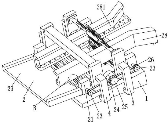
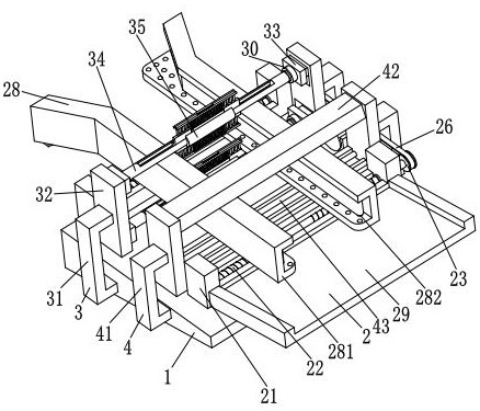
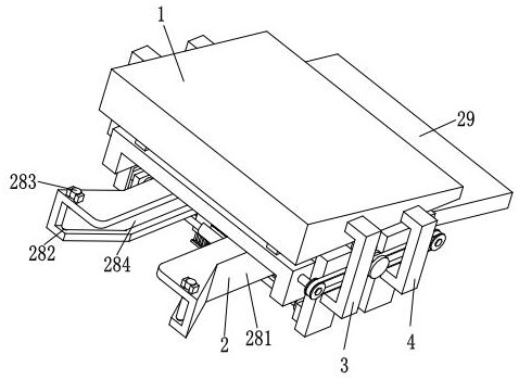
[0030] refer to figure 1 , figure 2 and image 3 , a kind of surface treatment equipment for circuit board manufacturing, comprising a bottom plate 1, a material guide device 2, an oiling device 3 and a drying device 4; The surface is symmetrically provided with a rectangular chute, the material guide device 2 is arranged in the rectangular chute of the bottom plate 1, and the upper end surface of the botto...


PUM


Abstract

The invention relates to the technical field of circuit board manufacturing and processing, in particular to surface treatment equipment for circuit board manufacturing. The equipment comprises a bottom plate, a material guiding device, an oiling device and a drying device. The invention solves the problems that in the existing circuit board oil brushing process, a whole board is usually cut into various small boards of different models to be manufactured into circuit boards, the distance of a limiting unit is inconvenient to adjust to fix the circuit board in the circuit board machining process, and the circuit board machining efficiency is low; the problems that when oil is brushed on the surfaces of circuit boards with different sizes, the size of a brush head is difficult to adjust to enable the size of the brush head to be matched with that of the circuit boards, and the oil on the surfaces of the circuit boards cannot be brushed or the oil on the brush head drips on the circuit boards due to non-uniform oil in the process of brushing the oil on the circuit boards by the brush head are solved. The oil brushing effect on the surface of the circuit board is improved, and surface treatment of circuit boards of various models is facilitated.

Description

technical field [0001] The invention relates to the technical field of circuit board manufacturing and processing, in particular to surface treatment equipment for circuit board manufacturing. Background technique [0002] Electronic components are components of electronic components and small machines and instruments. They are often composed of several parts and can be used in similar products; they often refer to certain parts in industries such as electrical appliances, radios, and instruments. They are capacitors, transistors, The general term for electronic devices such as hairsprings and springs; common ones include diodes, ceramic magnetic materials, circuit boards, resistors, capacitors, etc. [0003] In the circuit board manufacturing process, a whole board is usually cut into several small pieces, and the surface of the board is polished and etched by a machine, and then oiled again. The purpose of oiling is to prevent internal circuits from interfering It plays a...

Claims


Application Information

Patent Timeline
Patent Type & Authority Applications(China)
IPC IPC(8): H05K3/22H05K3/28
CPCH05K3/227H05K3/28
Inventor 陈亚南
Owner 江苏特塑新能源科技有限公司
Learn More