Fishpond feeding device
A feeding device and fish pond technology, applied in the field of breeding, can solve the problems of being unable to use the wind to drive the device to feed feed, and hindering the feed from leaking out of the outlet, so as to prevent poor breeding effect, improve feeding effect, and prevent diffusion overflow effect
- Summary
- Abstract
- Description
- Claims
- Application Information
AI Technical Summary
Problems solved by technology
Method used
Image

Examples
Embodiment 1
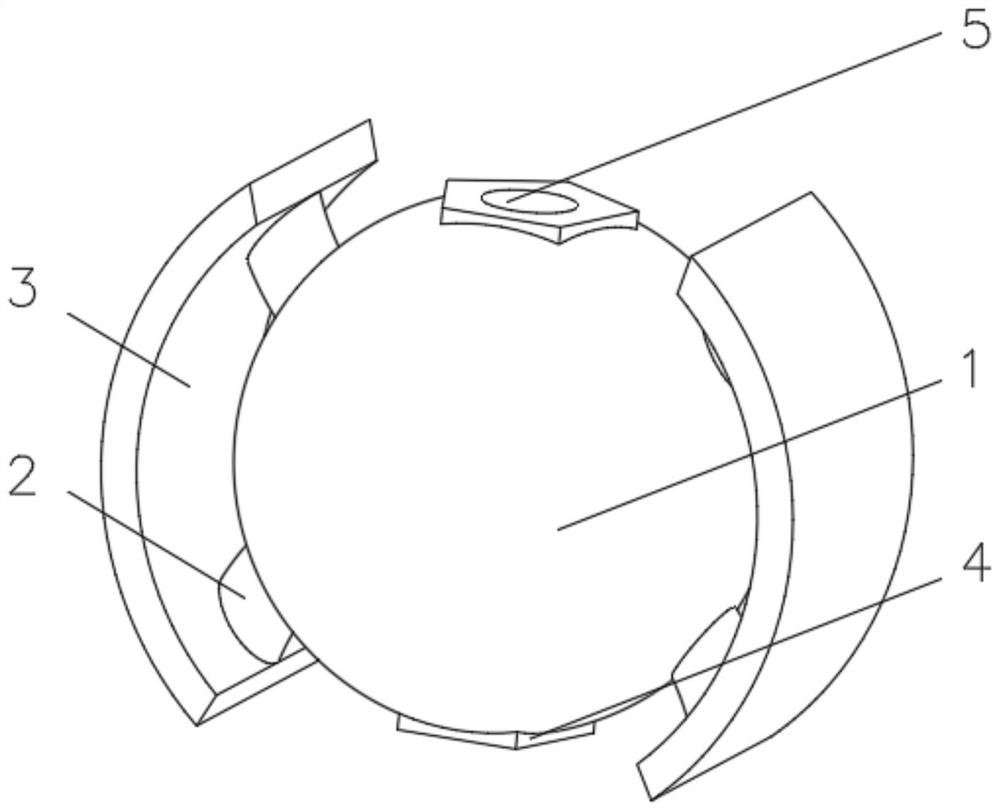
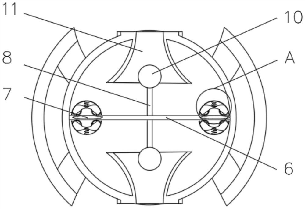
[0030] see Figure 1-3 , the present invention provides a technical solution: a fish pond feeding device, including a floating ball 1, a support frame 2 is symmetrically installed on one side of the floating ball 1, and a buoyancy plate 3 is fixedly connected to the end of the support frame 2 away from the floating ball 1 One side of the floating ball 1 is symmetrically provided with a charging port 4, and the side of the charging port 4 away from the floating ball 1 is provided with a discharge port 5, and the inner wall of the floating ball 1 is fixedly connected with a partition plate 6, which is hollow The inside of the partition board 6 is slidingly connected with a first magnet block 7, one side of the partition board 6 is symmetrically installed with a connecting rope 8, and one side of the partition board 6 is symmetrically installed with a scraper device 9.
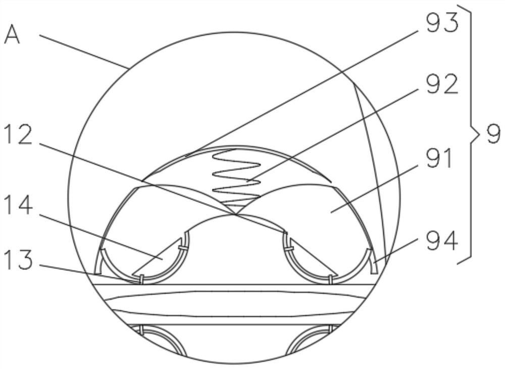
[0031] The scraping device 9 includes a device frame 91, a spring 92 is fixedly connected to one side of the d...
Embodiment 2
[0036] see Figure 1-4 , the present invention provides a technical solution: on the basis of Embodiment 1, the end of the connecting rope 8 away from the partition plate 6 is fixedly connected with a volume control device 10, the volume control device 10 includes a housing 101, and the housing 101 is fixedly connected with the connecting rope 8 , one side of the casing 101 is symmetrically installed with an elastic soft board 102 , and the inside of the casing 101 is filled with yellow sand 103 .
[0037]The side of the elastic soft board 102 away from the shell 101 is fixedly connected with an elastic rod 104, and the end of the firm elastic rod 104 away from the elastic soft board 102 is fixedly connected with an arc-shaped push plate 105, and the side of the arc-shaped push plate 105 away from the elastic rod 104 Rubber blocks 106 are evenly installed.
[0038] When in use, the connecting rope 8 drives the shell 101 to shake, and when the rubber block 106 touches the inne...
Embodiment 3
[0040] see Figure 1-5 , the present invention provides a kind of technical scheme: on the basis of embodiment two, the inner wall of floating ball 1 is symmetrically installed with discharging device 11 near the position of charging port 4, and discharging device 11 comprises discharging frame 111, and discharging frame One side of 111 is fixedly connected with an elastic net 112 , and the side of the discharge frame 111 close to the elastic net 112 communicates with the discharge port 5 .
[0041] The inner wall of the discharge frame 111 is symmetrically equipped with an arc-shaped elastic rod 113, and one end of the arc-shaped elastic rod 113 away from the discharge frame 111 is fixedly connected with a push rod 114, and one end of the push rod 114 is rotationally connected with the discharge frame 111, and the push rod 114 A groove 115 is evenly formed on a side away from the arc-shaped elastic rod 113 .
[0042] During use, the feed slides down to the discharge port 5 t...
PUM
 Abstract
Description
Claims
Application Information
 - R&D
- Intellectual Property
- Life Sciences
- Materials
- Tech Scout
- Unparalleled Data Quality
- Higher Quality Content
- 60% Fewer Hallucinations
Browse by: Latest US Patents, China's latest patents, Technical Efficacy Thesaurus, Application Domain, Technology Topic, Popular Technical Reports.
© 2025 PatSnap. All rights reserved.Legal|Privacy policy|Modern Slavery Act Transparency Statement|Sitemap|About US| Contact US: help@patsnap.com