Dehumidifying and dust-prevention device of generator set winding

A technology for generating sets and dust-proof devices, applied in the directions of using liquid separation agent, gas treatment, membrane technology, etc., can solve the problems of increasing air humidity, large bubble volume, and reducing bubbles, etc.

Pending Publication Date: 2021-10-01
三沙供电局有限责任公司
View PDF7 Cites 0 Cited by
  • Summary
  • Abstract
  • Description
  • Claims
  • Application Information

AI Technical Summary

Problems solved by technology

However, the use of moisture-removing and dust-proof devices for generator windings is very limited. For example, the use of diesel generators on the island is affected by the marine climate environment all year round, which makes the air on the island contain a lot of humidity and salt.
Humidity and salt in the air reduce the insulation of the electric ball winding of the generator set, thereby breaking down the insulation of the electric ball winding and making the generator set unable to operate
The existing technology uses spraying or underwater aeration to remove the salt in the air. When spraying is used, the humidity of the air will be greatly increased, which will easily cause short circuit of the generator set; when using underwater aeration, the current The volume of air bubbles produced by some aeration devices is too large, and the air bubbles are subjected to resistance after being discharged from the aeration tube. , making the volume of the bubbles further increase, which is not conducive to the removal of salt in the air

Method used


Image

  • Dehumidifying and dust-prevention device of generator set winding
  • Dehumidifying and dust-prevention device of generator set winding

Examples


Embodiment Construction

[0018] In order to better understand the technical content of the present invention, specific embodiments are provided below, and the present invention is further described in conjunction with the accompanying drawings.

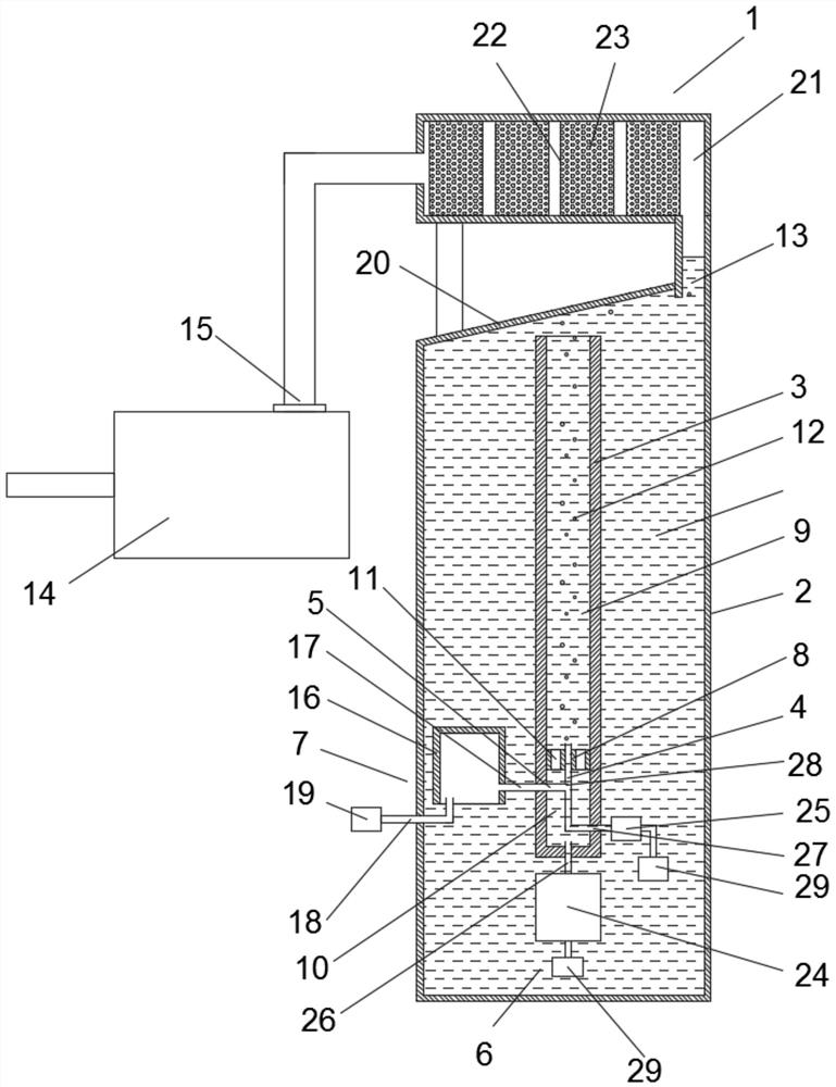
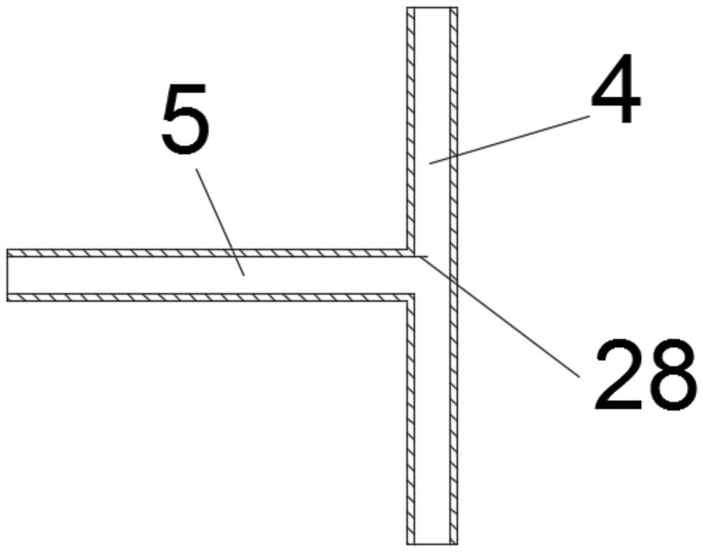
[0019] see Figure 1~2 , a dehumidification and dust-proof device for generator set windings, comprising a drying tank 1, a water tank 2, a water pipe 3, a first needle tube 4, a second needle tube 5, a water pumping device 6 and an air supply device 7, and the water tank 2 is equipped with Cooling water, the water pipe 3 is located in the water tank 2, the two ends of the water pipe 3 are provided with openings, the water pipe 3 is provided with a water pipe 3 into the first cavity 9 and the second cavity 10 The isolation plate 8 is provided with a plurality of through holes 11 communicating with the first cavity 9 and the second cavity 10, and the first needle tube 4 passes through the middle of the isolation plate 8 to communicate with the first cavity 9 a...


PUM

PropertyMeasurementUnit
Diameteraaaaaaaaaa

Abstract

The invention relates to a dehumidification and dust-prevention device of generator set winding, which comprises a drying tank, a water tank, a water pipe, a first needle tube, a second needle tube, a water pumping device and an air supply device, an isolation plate dividing the water pipe into a first cavity and a second cavity is arranged in the water pipe, and the first needle tube penetrates through the middle of the isolation plate to communicate the first cavity with the second cavity; the middle of the first needle tube is communicated with the second needle tube, the second needle tube is communicated with the air supply device, the first cavity and the first needle tube are communicated with the water pumping device, and the water flow speed in the first needle tube is smaller than or equal to that in the water pipe. When water flow in the first needle tube passes through the communicating position of the first needle tube and the second needle tube, air flowing out of the second needle tube is cut into a plurality of bubbles, an exhaust port communicating with the drying tank is formed in the top of the water tank, and the drying tank is provided with a connector communicating with a generator shell. According to the invention, moisture, dust and salt in air can be effectively removed, and the service life of the generator set is prolonged.

Description

technical field [0001] The invention relates to the technical field of generator set auxiliary equipment, in particular to a moisture-removing and dust-proof device for generator set windings. Background technique [0002] During the working process of the generator set, the temperature of the motor winding will rise, in order to ensure that the motor winding works within a suitable temperature range. Usually, gas is filled into the casing of the generator, and the heat in the generator winding is taken away by the flow of gas, thereby reducing the temperature of the generator winding. The dehumidification and dust-proof device of the generator set winding can remove dust and moisture from the air before the cooled air enters the generator, so as to avoid the short circuit of the generator winding caused by dust and water vapor in the air. However, the use of moisture-removing and dust-proof devices for generator windings is very limited. For example, diesel generators used...

Claims


Application Information

Patent Timeline
IPC IPC(8): B01D53/26B01D47/02
CPCB01D53/265B01D47/021B01D2257/80
Inventor 赵景飞刘获陈超邓莩铠李重康红伟王炜明
Owner 三沙供电局有限责任公司
Why Eureka
Try Eureka