method for manufacturing Cu-Ni-Sn-Sn alloy and cooler for Cu-Ni-Sn alloy
A cu-ni-sn, manufacturing method technology, applied in the field of coolers, can solve the problems of unsuitable multi-variety production, etc.
- Summary
- Abstract
- Description
- Claims
- Application Information
AI Technical Summary
Problems solved by technology
Method used
Image
Examples
example 1
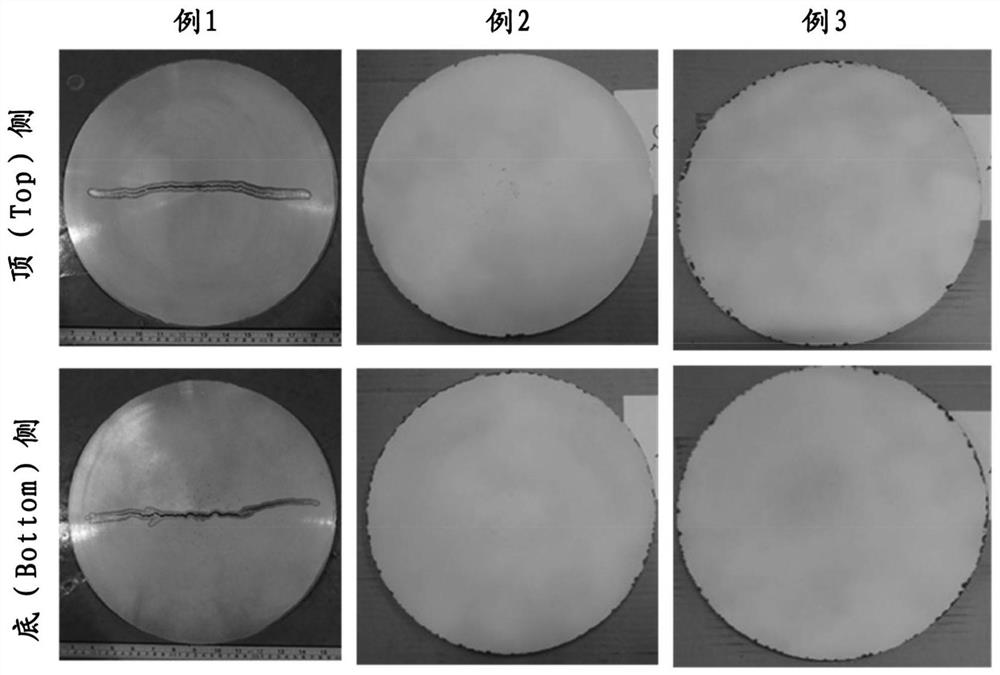
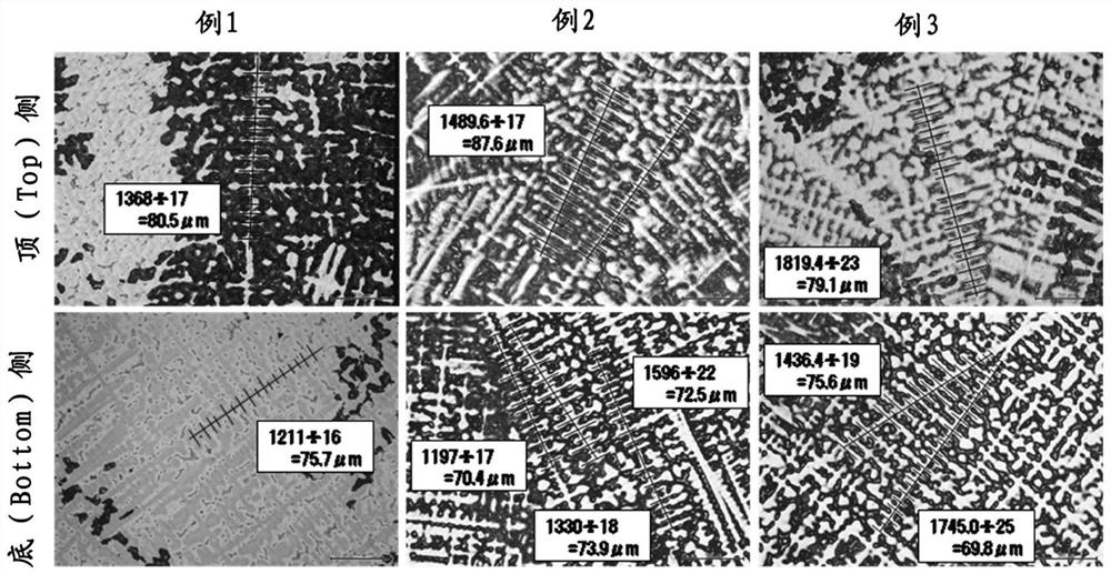
[0041] example 1 (Compare)
[0042] As a Cu—Ni—Sn alloy, a Cu—15Ni—8Sn alloy specified in UNS: C72900 was prepared and evaluated by the following procedure.
[0043] (1) weighing
[0044] A pure Cu nugget, a Ni matrix, a Sn matrix, electrical manganese, and Cu—Ni—Sn alloy scrap, which are raw materials of the Cu—Ni—Sn alloy, were weighed so as to have a target composition. That is, 163 kg of Cu, 30 kg of Ni, 15 kg of Sn, and 1450 kg of Cu—Ni—Sn alloy scrap were weighed and mixed to prepare them.
[0045] (2) Melting and slag treatment
[0046] The weighed raw material of Cu—Ni—Sn alloy was melted at 1200 to 1400° C. in an atmospheric high-frequency melting furnace, and stirred for 30 minutes to homogenize the components. After the melting is completed, slag scraping and slag scooping are carried out.
[0047] (3) Composition analysis (before casting)
[0048] A part of the Cu—Ni—Sn alloy obtained by melting and slag treatment was collected as a sample for component anal...
example 2
[0062] Instead of water cooling in (5) above, preparation and evaluation of samples were performed in the same manner as in Example 1 except that spray cooling was performed as follows. The size of the obtained cast product was 320 mm in diameter x 2 m in length.
[0063] (5') cooling (spray cooling)
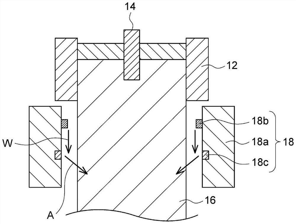
[0064] Such as figure 1 As shown schematically, the solidified ingot 16 is continuously drawn out while blowing mist water through the cooler 18 provided directly under the mold 12 . At this time, 7 to 13 L / min of water W is dripped from the water supply part 18b located on the upper part of the cylindrical main body 18a of the cooler 18, and the water W from the cylindrical main body 18a provided on the cooler 18 as the air injection part 18c The downstream 120 holes with a diameter of 3.5 mm are blown with air A at a pressure of 2.7 to 3.3 MPa, thereby atomizing the dripped water W to form mist water (that is, spray), and blowing it to the ingot 16 . In addition, the ingot ...
example 3
[0065] Example 3 (Compare)
[0066] Instead of spray cooling in (5) above, preparation and evaluation of samples were performed in the same manner as in Example 1 except that air cooling was performed as follows. The size of the obtained cast product was 320 mm in diameter x 2 m in length.
[0067] (5") cooling (air cooled)
[0068] The solidified ingot was continuously extracted while blowing air through a cooler installed directly under the mold. At this time, air was blown from 120 holes with a diameter of 3.5 mm provided in the cylindrical main body of the cooler, and the ingot was lowered while receiving it on a receiving table that lowered at 25 mm / min. By such a cooling method, after the semi-continuous casting of (4) above, the ingot was cooled to 50° C. over 12 hours. In the case of air cooling, since the cooling rate of the ingot is slow, internal cracks hardly occur, but it takes a long time for cooling, so it can be said that productivity is poor.
[0069] In...
PUM
 Abstract
Description
Claims
Application Information
 - R&D
- Intellectual Property
- Life Sciences
- Materials
- Tech Scout
- Unparalleled Data Quality
- Higher Quality Content
- 60% Fewer Hallucinations
Browse by: Latest US Patents, China's latest patents, Technical Efficacy Thesaurus, Application Domain, Technology Topic, Popular Technical Reports.
© 2025 PatSnap. All rights reserved.Legal|Privacy policy|Modern Slavery Act Transparency Statement|Sitemap|About US| Contact US: help@patsnap.com


