Rigid clamping system of grooving cutter
A slotting knife and rigid technology, applied in the accessories of tool holders, tools for lathes, turning equipment, etc., can solve the problems of narrow application range of slotting knives, narrow application range, and unfavorable production, so as to reduce tool inventory and manufacture Simplicity and the effect of reducing tool costs
- Summary
- Abstract
- Description
- Claims
- Application Information
AI Technical Summary
Problems solved by technology
Method used
Image

Examples
Embodiment 1
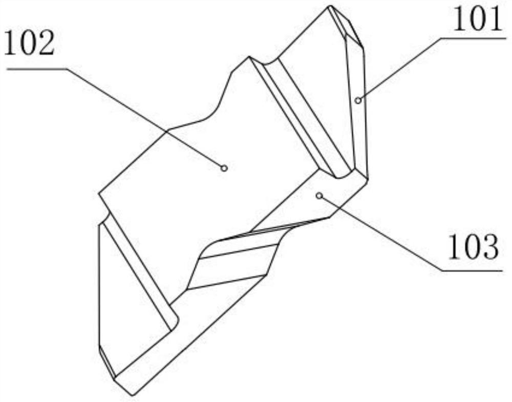
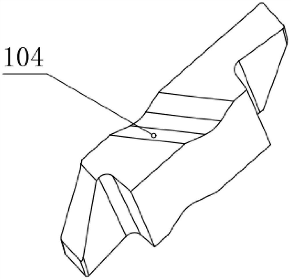
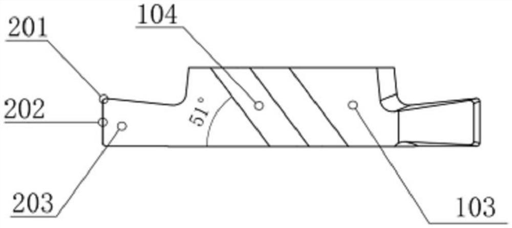
[0028]Example 1: See Figure 1 to Figure 6 , the invention discloses a rigid clamping system for a slot cutter, comprising a slot cutter 1 and a clamp 2 for fixing the slot cutter 1, the slot cutter 1 includes a clamping part 104 and is arranged on the clamping part The clamping part 104 on 104, the clamping part 104 and the clamping part 104 are integrally structured, the clamping part 104 includes a side positioning surface 102, an oblique positioning surface 101 and a lower positioning surface 103, the groove The knife 1 is also provided with an outer surface parallel to the side positioning surface 102, and the slot knife 1 is also provided with an upper plane parallel to the lower positioning surface 103. The lower positioning surface 103 and the upper plane Both sides of the clamping part 104 are provided with the clamping part 104; both sides of the clamping part 104 are provided with cutting parts, the inclined positioning surface 101 is arranged on the cutting part, t...
Embodiment 2
[0030] Example 2: see Figure 1 to Figure 6 , the fixture 2 in this embodiment is provided with a fixing groove, and the fixing groove includes a first fixing surface, a second fixing surface and a fixing slope adjacent to each other, and the first fixing surface abuts against the side positioning surface 102 The second fixed surface is fixed against the lower positioning surface 103 , and the fixed inclined surface is fixed against the inclined positioning surface 101 . The side positioning surface 102, the oblique positioning surface 101 and the lower positioning surface 103 respectively resist against the first fixing surface, the second fixing surface and the fixing inclined surface to realize 6-point positioning of the blade, and the positioning method is simple and practical. 6-point positioning on 3 sides can disperse cutting resistance and improve tool life.
Embodiment 3
[0031] Example 3: See Figure 1 to Figure 6 In this embodiment, the first fixing surface and the second fixing surface are perpendicular to each other, and the side positioning surface 102 and the lower positioning surface 103 are also perpendicular to each other. It can ensure that the blade can be positioned more accurately. In this embodiment, the second fixing surface is provided with a fixing part corresponding to the clamping part 104, and the clamp 2 also includes a pressing claw 21 for fixing the clamping part 104 of the upper plane, and further Groove cutter 1 is limited. The grooving cutter 1 can be fixed in a limit to prevent the grooving cutter 1 from slipping during processing. Pressing claw 21 is movable detachable type.
PUM
| Property | Measurement | Unit |
|---|---|---|
| Angle | aaaaa | aaaaa |
| Angle | aaaaa | aaaaa |
Abstract
Description
Claims
Application Information
 - R&D
- Intellectual Property
- Life Sciences
- Materials
- Tech Scout
- Unparalleled Data Quality
- Higher Quality Content
- 60% Fewer Hallucinations
Browse by: Latest US Patents, China's latest patents, Technical Efficacy Thesaurus, Application Domain, Technology Topic, Popular Technical Reports.
© 2025 PatSnap. All rights reserved.Legal|Privacy policy|Modern Slavery Act Transparency Statement|Sitemap|About US| Contact US: help@patsnap.com