Traveling device of automatic welding tractor

An automatic welding and walking device technology, which is applied in the field of welding manufacturing, can solve problems such as increased labor and material costs, failure to work normally, deviation, etc., to improve welding quality and efficiency, save labor costs and time, and ensure construction quality Effect

Pending Publication Date: 2021-10-01
NANJING CHINA CONSTR CHEM EQUIP MFG +1
View PDF7 Cites 0 Cited by
  • Summary
  • Abstract
  • Description
  • Claims
  • Application Information

AI Technical Summary

Problems solved by technology

[0002] The existing automatic welding trolley cannot weld a section of the weld seam on the plane at both ends of the workpiece. It is necessary to manually add an auxiliary plate to weld and lengthen the two ends of the workpiece. A section of welding seam is determined by the structure of the automatic welding trolley, which cannot be overcome at present. This welding method increases labor costs and material costs, and the efficiency is extremely low
[0003] The existing automatic welding trolley cannot always walk along a straight line during the working process, and often deviates; during the welding process, since the guide wheel of the automatic welding trolley only leans against the side of the workpiece, there is no external force to correct the deviation of the trolley , it is necessary to stop the welding work, after manual calibration, and then restart the equipment again, the weld will be disconnected, which will affect the welding quality and work efficiency
[0004] In addition, because the welding seam will generate high temperature during the welding process, the rubber wheels of the subsequent automatic welding trolley will burn out and cannot work normally. Therefore, it is impossible to use multiple automatic welding trolleys for welding at the same time, which is not conducive to the improvement of work efficiency.

Method used


Image

  • Traveling device of automatic welding tractor
  • Traveling device of automatic welding tractor
  • Traveling device of automatic welding tractor

Examples


Embodiment 1

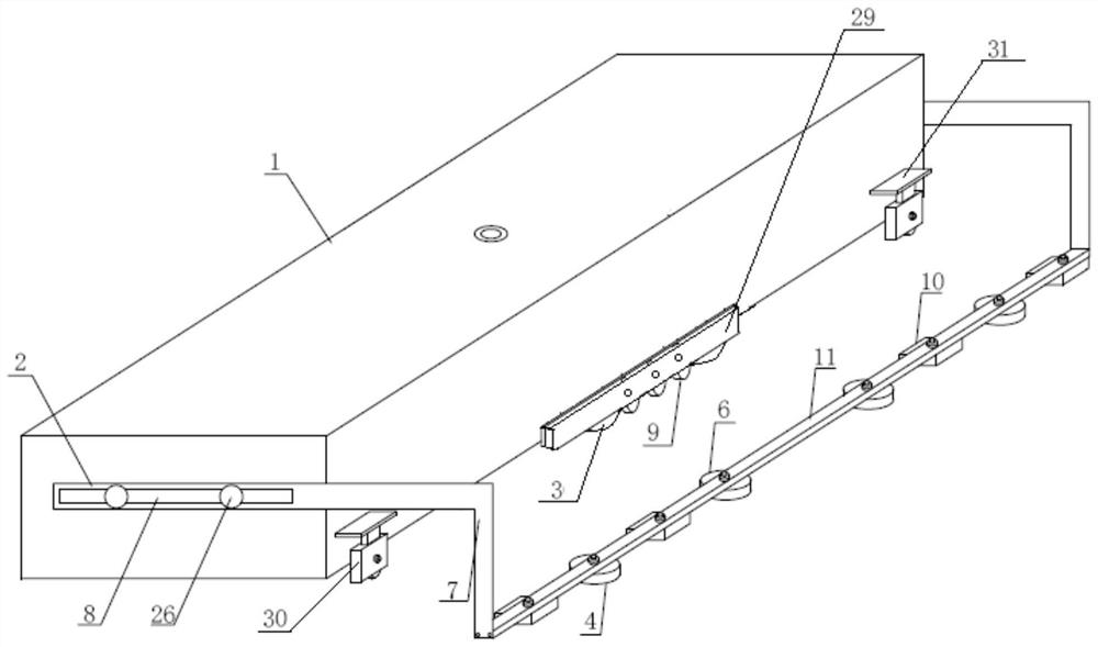
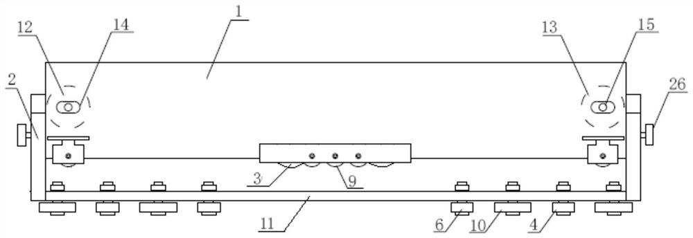
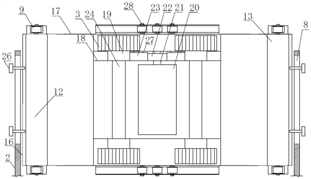
[0032] Such as figure 1 , 2 , 3, the walking device of the automatic welding trolley of the present invention comprises an automatic welding trolley body 1, the bottom of the car body 1 is open, and a first magnetic base 12 and a second magnetic base 13 are respectively installed at both ends of the interior of the vehicle body 1 , the first magnetic base switch 14 and the second magnetic base switch 15 are all arranged on the left side of the vehicle body.

[0033] Such as figure 1 , 3 , 4, on the end plate 16 at both ends of the car body 1, a guide arm 2 is installed horizontally, and the surface of one end of the guide arm 2 is provided with a notch 8, and the screw 26 passes through the notch 8 to fix one end of the guide arm 2 on the end plate 16; the other end of the guide arm 2 stretches out to the right side of the car body 1 and is equipped with a straight bar 7 vertically downward. A guide rod 11 is installed between the two straight rods 7 at the two ends of the...

Embodiment 2

[0042] In this embodiment, on the basis of Embodiment 1, the walking drive mechanism has been improved, as follows:

[0043] Such as Figure 5 , 6 As shown, crawler belt 25 is installed on the driving wheel 3 of the traveling drive mechanism, and the inner surface of driving wheel 3 coincides with the inner surface of crawler belt 25; .

[0044] The crawler belt 25 is made of metal or non-metallic material; when metal material is used to make the crawler belt 25, a pattern structure is arranged on the outer surface of the crawler belt 25, which can effectively increase the friction between it and the workpiece 5; When crawler belt 25, present embodiment is preferred to make crawler belt 25 with steel wire and high-temperature-resistant rubber as the material of filling molding with internal reinforcement, and a layer of gravel grain is evenly embedded in the outer layer of crawler belt 25, can strengthen crawler belt 25 surface anti-high temperature ability and with Frictio...


PUM


Abstract

The invention provides a traveling device of an automatic welding tractor. The traveling device comprises an automatic welding tractor body with magnetic bases at two ends inside, guide arms are installed at two ends of the outer side of the tractor body, the other ends of the guide arms extend to the right side of the tractor body and are provided with straight rods, a guide rod is installed between the two straight rods, and a plurality of guide wheels and magnetic blocks are installed on the lower surfaces of the two ends of the guide rod at intervals through bolts; and traveling wheels are installed on the two sides, close to the guide arms, of the tractor body, a traveling driving mechanism is installed in the middle of the tractor body, the traveling driving mechanism drives gears to conduct transmission through a motor, and therefore, a plurality of driving wheels and the traveling wheels installed in the middle of the tractor body are driven to travel, and the automatic traveling function of the welding tractor is achieved. The attraction force of the magnetic bases to the upper surface of a workpiece and the attraction force of the magnetic blocks to the side face of the workpiece jointly guarantee that the automatic welding tractor stably runs on the surface of the workpiece along a straight line all the time and cannot fall or turn over, all welding seams at the end of the workpiece are welded at a time, the welding quality is good, and the efficiency is high.

Description

technical field [0001] The invention belongs to the field of welding manufacturing technology, in particular to a running device of an automatic welding trolley. Background technique [0002] The existing automatic welding trolley cannot weld a section of the weld seam on the plane at both ends of the workpiece. It is necessary to manually add an auxiliary plate to weld and lengthen the two ends of the workpiece. A section of welding seam is determined by the structure of the automatic welding trolley, which cannot be overcome at present. This welding method increases labor costs and material costs, and the efficiency is extremely low. [0003] The existing automatic welding trolley cannot always walk along a straight line during the working process, and often deviates; during the welding process, since the guide wheel of the automatic welding trolley only leans against the side of the workpiece, there is no external force to correct the deviation of the trolley , It is nec...

Claims


Application Information

Patent Timeline
Patent Type & Authority Applications(China)
IPC IPC(8): B23K37/02
CPCB23K37/0294
Inventor 陈晓蓉吴承贵王洪福李乐校荣桂程溢清杨九洲马亮金远健朱宇君葛一帅徐文斌陶双双任洁孙永杰赵锦欣杨红季可朋吴纹龙杨申国
Owner NANJING CHINA CONSTR CHEM EQUIP MFG
Why Eureka
Try Eureka