
An automatic cutting system

A cutting system and driving device technology, applied in the direction of manufacturing tools, metal processing machinery parts, positioning devices, etc., can solve the problems affecting the quality of processed products, the impact of workers' working environment, and the low degree of automation, so as to save space and improve product quality , the effect of improving the degree of automation

Active Publication Date: 2022-05-10
绍兴上虞舜宏化工设备有限公司
View PDF0 Cites 0 Cited by
  • Summary
  • Abstract
  • Description
  • Claims
  • Application Information

AI Technical Summary

Problems solved by technology

[0002] The existing automatic cutting device has a low degree of automation, mainly through manual control of positioning and manual control of cutting, and then the method of collecting waste chips after cutting is not good, just use a collection box to collect waste chips all the time, and There will be more and more waste in the collection box, and the collection box needs to be disassembled manually to process the waste inside, but this method is very troublesome and the degree of automation is not high. If it is not processed in time, it will lead to waste Chips fly outside, affecting the quality of processed products and affecting the working environment of workers

Method used


Image

  • An automatic cutting system
  • An automatic cutting system
  • An automatic cutting system

Examples


Embodiment Construction

[0032] In order to enable those skilled in the art to better understand the solutions of the present invention, the technical solutions in the embodiments of the present invention will be clearly and completely described below in conjunction with the drawings in the embodiments of the present invention.

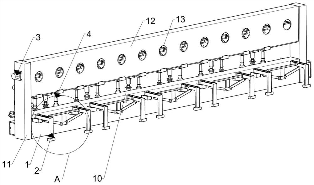
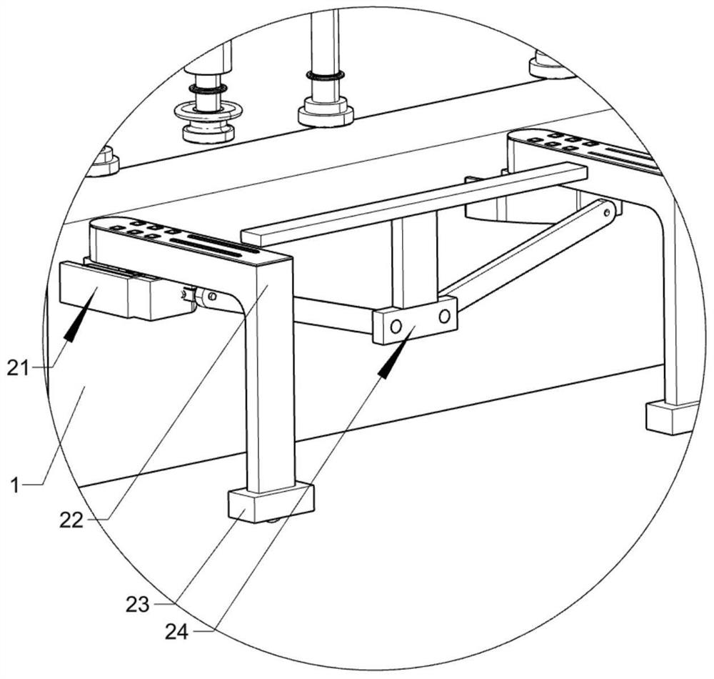
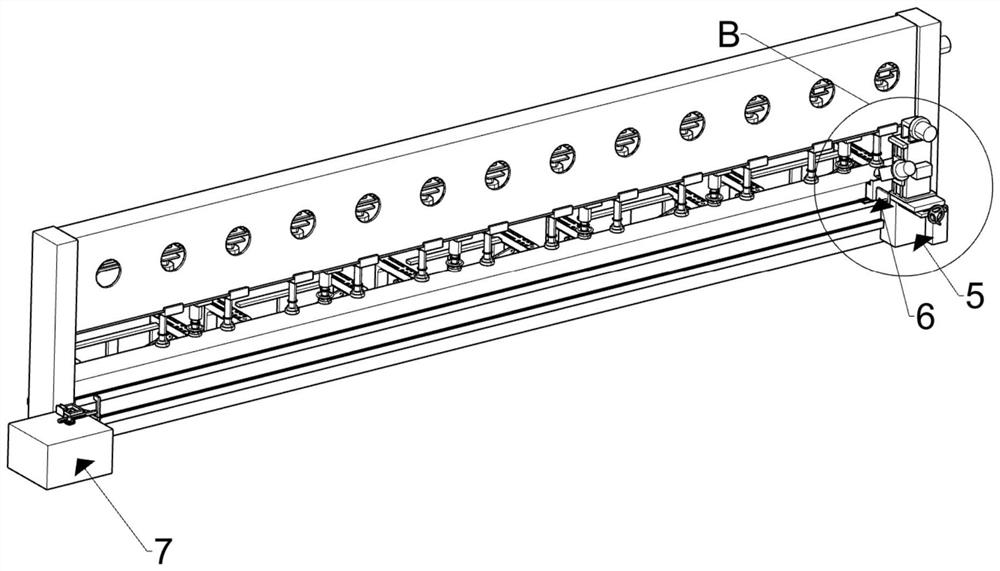
[0033] Such as Figure 1-20 As shown, an automatic cutting system includes a workbench 1 for supporting parts to be processed, a first support 11 fixedly arranged on both sides of the workbench 1, a first support 11 arranged above the workbench 1 and connected to the first support 11 The second support member 12, a plurality of circular through holes 13 arranged on the second support member 12, a hydraulic cylinder 4 arranged between every two circular through holes 13, a side of the workbench 1 and The supporting device 2 in contact with the ground, the drive device 5 that is arranged on the other side of the workbench 1 and can slide on the workbench 1, the first waste coll...


PUM


Abstract

The invention discloses an automatic cutting system, which comprises a workbench, a hydraulic cylinder, a supporting device arranged on one side of the workbench and in contact with the ground, and a support device arranged on the other side of the workbench and capable of sliding on the workbench The driving device, the first waste collecting device connected to the driving device, the second waste collecting device set at the limit position when the driving device slides and fixed on the workbench; the hydraulic cylinder includes an adjustable preload assembly; by setting The support device can support parts of different sizes; the first waste collection device and the second waste collection device are set up to collect waste and discard them regularly during collection to keep collecting waste The inside of the first collection box is clean, which makes the collection of waste chips better. The present invention improves the degree of automation by automatically realizing the collection and cleaning of waste chips.

Description

technical field [0001] The invention belongs to the technical field of mechanical processing, and in particular relates to an automatic cutting system. Background technique [0002] The existing automatic cutting device has a low degree of automation, mainly through manual control of positioning and manual control of cutting, and then the method of collecting waste chips after cutting is not good, just use a collection box to collect waste chips all the time, and There will be more and more waste in the collection box, and the collection box needs to be disassembled manually to process the waste inside, but this method is very troublesome and the degree of automation is not high. If it is not processed in time, it will lead to waste Chips fly outside, affecting the quality of processed products and affecting the working environment of workers. Contents of the invention [0003] In order to overcome the deficiencies of the prior art, the present invention provides an autom...

Claims


Application Information

Patent Timeline
Patent Type & Authority Patents(China)
IPC IPC(8): B23Q3/06B23Q11/00
CPCB23Q3/06B23Q11/0042
Inventor 赵星波金云水谢海燕梁勇王炜杜汉培王杰锋
Owner 绍兴上虞舜宏化工设备有限公司
Learn More