Capacitor shell stamping device

A stamping device and capacitor technology, which is applied in the direction of capacitors, capacitor manufacturing, grinding/polishing safety devices, etc., can solve the problems of inconvenient grinding of stamping seats, heating of stamping seats, hidden safety hazards, etc., to facilitate continuous processing and improve Stamping quality, consistent effect

Active Publication Date: 2021-10-01
南通海美电子有限公司
View PDF8 Cites 2 Cited by
  • Summary
  • Abstract
  • Description
  • Claims
  • Application Information

AI Technical Summary

Problems solved by technology

[0003] In the current process of stamping the capacitor shell, it is necessary to manually place the raw materials on the lower part of the stamping seat, or place them with the help of related equipment. The former has certain safety hazards, while the latter will generate more use costs; in the process of stamping In the process of stamping, due to the wear of the cutting edge of the stamping seat or the interference of debris generated by stamping, burrs of various shapes are prone to be produced during the stamping process. Such burrs cause certain processing difficulties to the subsequent process, and frequent rework occurs. It causes waste in production, and it is inconvenient to polish the stamping seat at present; finally, in the continuous stamping operation, it will also cause the stamping seat to continue to heat up, so that it is easy to produce a gap in the subsequent stamping

Method used


Image

  • Capacitor shell stamping device
  • Capacitor shell stamping device
  • Capacitor shell stamping device

Examples


Embodiment Construction

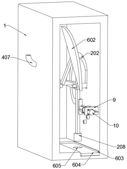
[0029] refer to figure 1 with Image 6 , a stamping device for a capacitor shell, comprising a box body 1, a first motor 5 is installed on the side wall of the box body 1, and a stamping mechanism is coaxially fixed at the output end of the first motor 5;

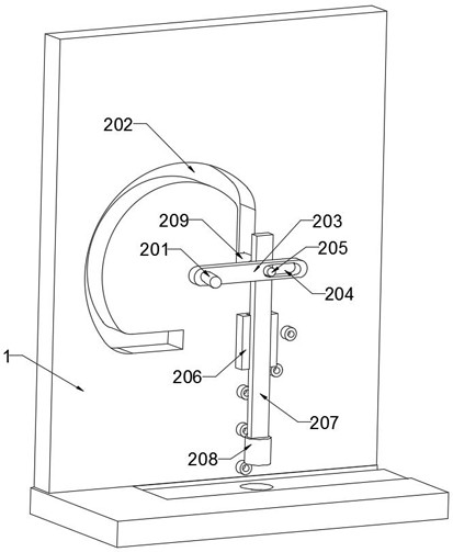
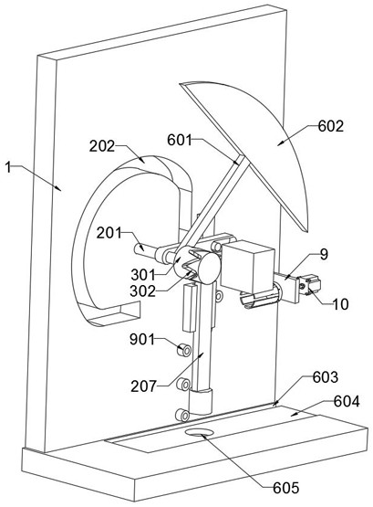
[0030] refer to Figure 2-3 , the stamping mechanism includes a rotating shaft 201 fixed coaxially with the output end of the first motor 5, the rotating shaft 201 penetrates the inner wall of the box body 1 and is fixedly connected with a connecting plate 203, the inner wall of the connecting plate 203 is provided with a through hole 204, and the side wall of the box body 1 is provided with a Combination hole 202, the inner side wall of box body 1 is rotatably connected with guide rail 206, inside guide rail 206 is slidingly connected with ejector rod 207, and the inner wall of ejector rod 207 is connected with hinge bolt 205, and hinge bolt 205 is slidably connected in through hole 204 and combination hole 202 , the out...


PUM


Abstract

The invention discloses a capacitor shell stamping device. The capacitor shell stamping device comprises a box body, a first motor is installed on the side wall of the box body, and a stamping mechanism is coaxially fixed to the output end of the first motor; the stamping mechanism comprises a rotating shaft coaxially fixed to the output end of the first motor, the rotating shaft penetrates through the inner wall of the box body and then is fixedly connected with a connecting plate, a through hole is formed in the inner wall of the connecting plate, a combination hole is formed in the side wall of the box body, a guide rail is rotationally connected to the inner side wall of the box body, an ejector rod is glidingly connected into the guide rail, and a hinge bolt is connected to the inner wall of the ejector rod in a penetrating mode and is glidingly connected into the through hole and the combination hole. Through forward and reverse rotation of the first motor, the ejector rod and a stamping seat are driven to firstly conduct stamping in the vertical direction, then the ejector rod is driven to move in the horizontal direction, thus an impact seat on the ejector rod is polished, the stamping seat can be polished to be sharp in time after each time of stamping, and burrs are prevented from being generated in the shell stamping process.

Description

technical field [0001] The invention relates to the technical field of capacitor processing, in particular to a stamping device for a capacitor casing. Background technique [0002] With the rapid development of electronic information technology, the upgrading speed of digital electronic products is getting faster and faster. The production and sales of consumer electronic products, mainly flat-panel TVs, notebook computers, digital cameras and other products, continue to grow, which drives the growth of the capacitor industry. [0003] In the current process of stamping the capacitor shell, it is necessary to manually place the raw materials on the lower part of the stamping seat, or place them with the help of related equipment. The former has certain safety hazards, while the latter will generate more use costs; in the process of stamping In the process of stamping, due to the wear of the cutting edge of the stamping seat or the interference of debris generated by stampin...

Claims


Application Information

Patent Timeline
Patent Type & Authority Applications(China)
IPC IPC(8): B24B19/20B24B41/00B24B27/00B24B55/06B24B41/06B21D22/02B08B5/02H01G13/00H01G2/10
CPCB24B19/20B24B41/005B24B27/0076B24B55/06B24B41/06B21D22/02B08B5/02H01G13/00H01G2/10
Inventor 邵淋锋
Owner 南通海美电子有限公司
Why Eureka
Try Eureka