Beverage bottle label separating method and beverage bottle label separating machine

A beverage bottle and label technology, which is applied in the field of beverage bottle label detachment method and beverage bottle label detachment machine, can solve the problem that the label is difficult to remove, and achieve the effect of improving the removal rate

Active Publication Date: 2021-10-01
SOUTH UNIVERSITY OF SCIENCE AND TECHNOLOGY OF CHINA
View PDF7 Cites 1 Cited by
  • Summary
  • Abstract
  • Description
  • Claims
  • Application Information

AI Technical Summary

Problems solved by technology

[0005] In view of the shortcomings of the prior art above, the purpose of the present invention is to provide a beverage bottle label removal method and a beverage bottle label removal machine, aiming to solve the problem that the label on the plastic bottle is difficult to remove in the prior art

Method used


Image

  • Beverage bottle label separating method and beverage bottle label separating machine
  • Beverage bottle label separating method and beverage bottle label separating machine
  • Beverage bottle label separating method and beverage bottle label separating machine

Examples


Embodiment 1

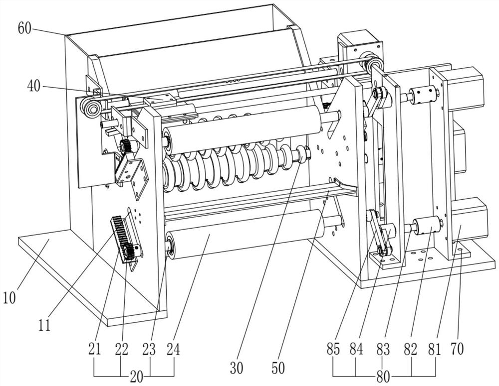
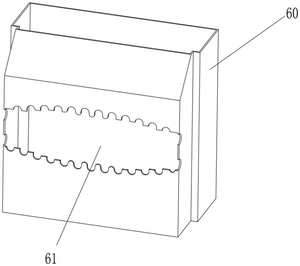
[0078] The invention discloses a beverage bottle label detaching machine, please refer to Figure 1 to Figure 4 . The beverage bottle label detaching machine includes: a frame 10, a movable roller assembly 20, a fixed roller assembly 30 and a cutting assembly 40; wherein, the frame 10 is a symmetrical structure, and two opposite sides of the frame 10 are located Symmetrically equipped with moving grooves; combined with figure 1 Description, the left side of the rack 10 is provided with two through moving grooves 11, the two moving grooves 11 are arranged in a cross (but not intersecting), and the two moving grooves 11 are arranged symmetrically with each other, and the rack 10 The right side is symmetrical with the left side, and the right side is also provided with the same moving groove 11 as the left side.

[0079] Further, the movable roller assemblies 20 are symmetrically arranged in the frame 10, and are gathered or separated through the moving grooves 11; that is, bot...

Embodiment 2

[0100] see Figure 7 , Based on the above-mentioned beverage bottle label detachment machine, the present invention also provides a beverage bottle label detachment method, which specifically includes the steps:

[0101] S100. Drive the movable roller assembly 20 to move along the moving groove 11 according to the size of the beverage bottle, so as to adjust the distance between the movable roller assemblies 20 and the distance between the movable roller assembly 20 and the fixed roller assembly 30, so that the The beverage bottle is clamped between the movable roller assembly 20 and the fixed roller assembly 30;

[0102] S200, driving the cutting assembly 40 to cut along the bottle body of the beverage bottle to separate the label from the beverage bottle;

[0103] S300 , the fixed roller assembly 30 is driven to rotate, and the label is pulled out from the beverage bottle through the frictional motion between the fixed roller assembly 30 and the label to complete the remova...


PUM


Abstract

The invention discloses a beverage bottle label separating method and a beverage bottle label separating machine. The beverage bottle label separating machine comprises a rack, movable roller assemblies, fixed roller assemblies and a cutting assembly, wherein moving grooves are symmetrically formed in the two opposite side faces of the rack; the movable roller assemblies are symmetrically arranged in the rack and are gathered or separated through the moving grooves; the fixed roller assemblies are symmetrically arranged in the rack and are engaged with each other to rotate; and the cutting assembly is arranged at the top of the rack and is located between the movable roller assemblies and the fixed roller assemblies. Beverage bottles with different sizes can be clamped through the movable roller assemblies and the fixed roller assemblies, then labels on the beverage bottles are cut once or multiple times through the cutting assembly, and then the labels are pulled out of the beverage bottles through friction between the fixed roller assemblies and the labels. According to the beverage bottle label separating machine in an embodiment of the invention, the labels on the beverage bottles can be completely removed, and the label removing rate is greatly increased.

Description

technical field [0001] The invention relates to the technical field of recovery and reuse, in particular to a beverage bottle label detachment method and a beverage bottle label detachment machine. Background technique [0002] With the increasing shortage of resources and the increasing severity of plastic pollution, the recycling and reuse of beverage bottles used by people as one of the main products of plastic consumption has been paid more and more attention by the society. In the recycling process of plastic bottles, it is necessary to separate the three materials of the bottle: the bottle body (PET), the label (PVC), and the bottle cap (PP, PE). The factory obtains PET with the highest purity as possible through separation to avoid impurities affecting the physical properties of recycled PET. Among them, PVC has the greatest impact on PET recycling. The thermal decomposition of PVC produces hydrogen chloride (HCl) as a catalyst to cause the hydrolysis of PET during ...

Claims


Application Information

Patent Timeline
Patent Type & Authority Applications(China)
IPC IPC(8): B29B17/02
CPCB29B17/02Y02W30/62
Inventor 尹容瑜何志豪
Owner SOUTH UNIVERSITY OF SCIENCE AND TECHNOLOGY OF CHINA
Why Eureka
Try Eureka