
Automatic laminating machine for circuit substrate and copper foil

A technology of circuit substrates and laminating machines, applied in lamination devices, lamination auxiliary operations, lamination, etc., can solve the problems of copper foil lamination, limited typesetting size, easy generation of air bubbles, copper foil warping, etc., to achieve Achieve automatic fit, ensure cleanliness, and avoid warping

Inactive Publication Date: 2021-10-01
HONGQISHENG PRECISION ELECTRONICS (QINHUANGDAO) CO LTD +1
View PDF7 Cites 1 Cited by
  • Summary
  • Abstract
  • Description
  • Claims
  • Application Information

AI Technical Summary

Problems solved by technology

In the prior art, jigs with positioning pins are often used for the lamination of substrates and copper foils, and the lamination is performed by manual positioning of the pins, and automatic lamination cannot be realized.
In addition, the bonding of copper foil is limited by the typesetting size, and the entire sheet needs to be bonded at one time
During the bonding process, the release paper on the copper foil is difficult to be torn off. If the release paper is torn off, the copper foil will warp during the bonding process, and air bubbles and wrinkles will easily occur during the bonding process. etc., thus affecting the bonding efficiency, bonding accuracy and quality of the substrate and copper foil

Method used


Image

  • Automatic laminating machine for circuit substrate and copper foil
  • Automatic laminating machine for circuit substrate and copper foil
  • Automatic laminating machine for circuit substrate and copper foil

Examples


Embodiment Construction

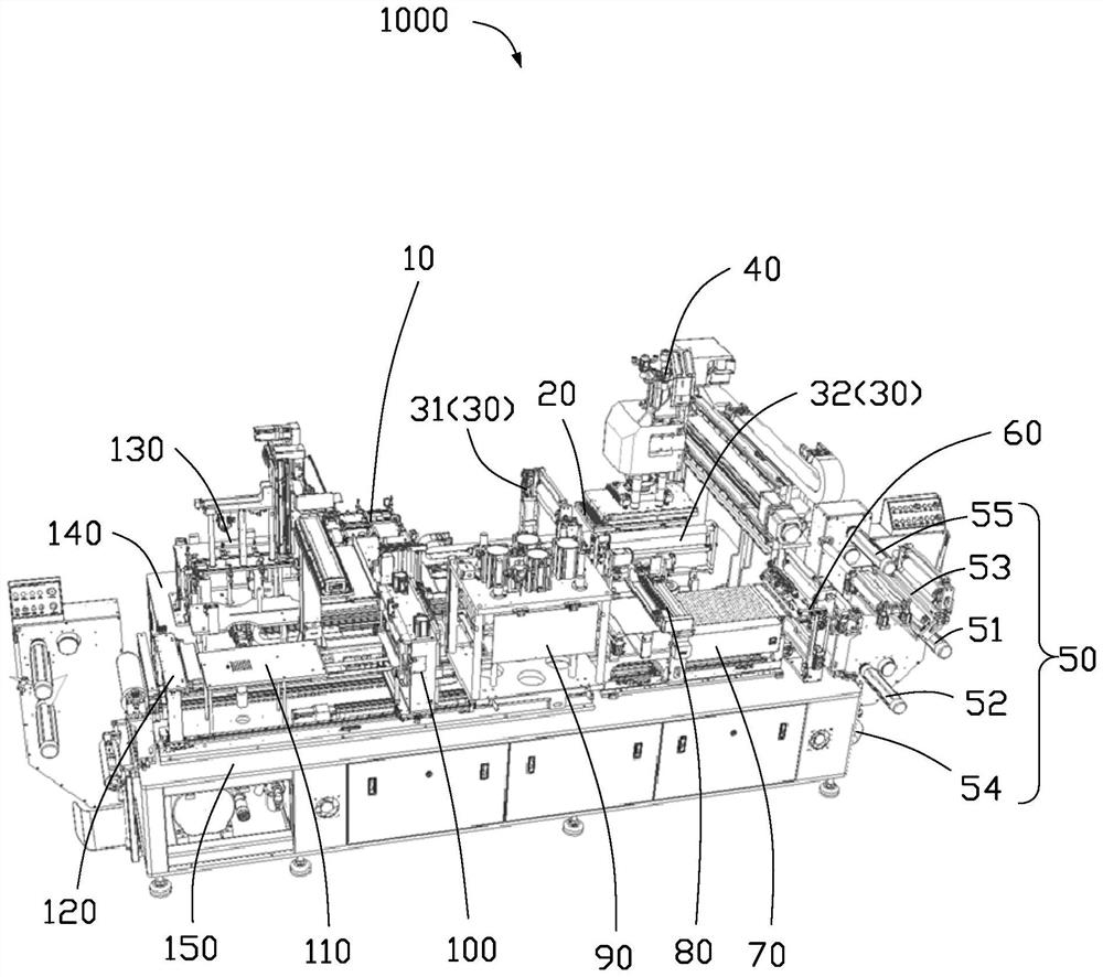
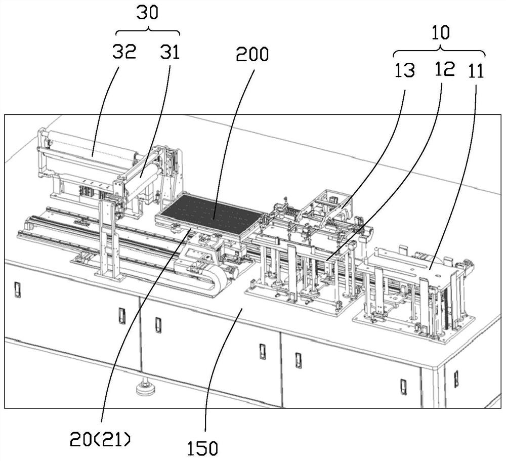
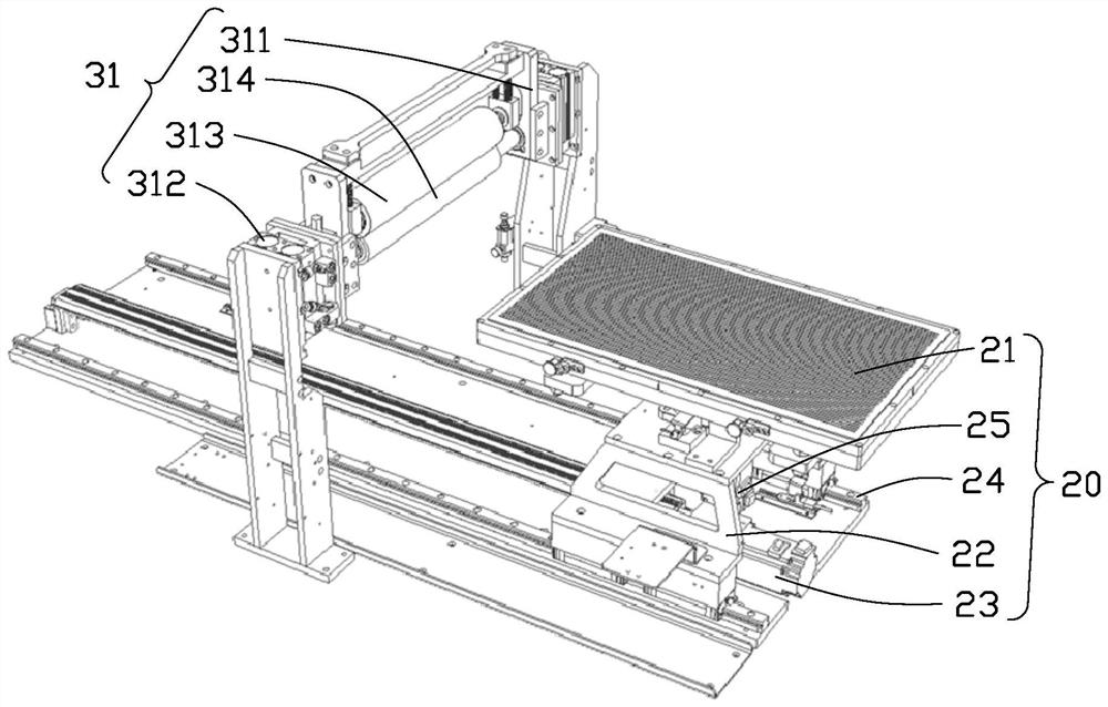
[0029] In order to further illustrate the technical means and effects that the present invention takes to reach the intended purpose of the invention, the following in conjunction with the appended Figure 1-8 And a preferred embodiment, the specific implementation, structure, features and effects of the substrate and copper foil automatic laminating machine provided by the present invention are described in detail as follows. Apparently, the described embodiments are only some of the embodiments of the present invention, but not all of them. Based on the embodiments of the present invention, all other embodiments obtained by persons of ordinary skill in the art without making creative efforts belong to the protection scope of the present invention.

[0030] It should be noted that when an element is considered to be "connected" to another element, it may be directly connected to the other element or there may be an intervening element at the same time. When an element is ref...


PUM


Abstract

An automatic laminating machine for a circuit substrate and a copper foil comprises: a copper foil cleaning device used for cleaning the copper foil; a false lamination platform used for false lamination of the substrate and the copper foil; a pre-pressing device used for pre-pressing the substrate and the copper foil; a clamping and pulling device used for fixing one end of the copper foil, pulling the copper foil after false lamination and pre-lamination, and moving the copper foil to a preset station; a roll type copper foil feeding device used for separating a copper foil and a release film in the roll type copper foil; a substrate transfer device used for transferring the substrate to a substrate to-be-sucked position; a substrate cleaning device positioned on one side of the substrate transfer device and used for cleaning the substrate on the transfer device; and a laminating suction cup device located between the substrate transfer device and the false attaching platform and used for sucking the substrate from the substrate transfer device, transferring the substrate to the position above the copper foil on the false attaching platform and enabling the substrate and the copper foil to be aligned and attached in a false mode. According to the automatic laminating machine for the circuit substrate and the copper foil, warping of the copper foil can be avoided, and bubbles and wrinkles are not prone to being generated.

Description

technical field [0001] The invention relates to the field of lamination of copper foil, in particular to an automatic lamination machine for circuit substrates and copper foil. Background technique [0002] In circuit board technology, the bonding of the substrate and the copper foil is essential. In the prior art, jigs with positioning pins are often used for the lamination of the substrate and copper foil, and the lamination is performed by manual positioning of the pins, and automatic lamination cannot be realized. In addition, the bonding of copper foil is limited by the typesetting size, and the entire sheet needs to be bonded at one time. During the bonding process, the release paper on the copper foil is difficult to be torn off. If the release paper is torn off, the copper foil will warp during the bonding process, and air bubbles and wrinkles will easily occur during the bonding process. etc., thereby affecting the bonding efficiency, bonding accuracy and quality ...

Claims


Application Information

Patent Timeline
Patent Type & Authority Applications(China)
IPC IPC(8): B32B37/10B32B38/00B32B38/16B32B38/10B32B38/18
CPCB32B37/10B32B38/0004B32B38/162B32B38/10B32B38/185
Inventor 潘广艺
Owner HONGQISHENG PRECISION ELECTRONICS (QINHUANGDAO) CO LTD
Learn More