Electronic brake booster

A technology of booster and motor rotor, applied in the field of brake devices, can solve problems such as unfavorable use of vehicle space and weight reduction, unfavorable precise control of brake booster, large size of electric power assist system, etc., to achieve accurate and fast processing and Feedback, less interference, the effect of simplifying the installation process

Active Publication Date: 2021-10-01
ZHEJIANG SANXING MECHANICAL & ELECTRONICSAL STOCK
View PDF6 Cites 0 Cited by
  • Summary
  • Abstract
  • Description
  • Claims
  • Application Information

AI Technical Summary

Problems solved by technology

[0002] At present, the electric power-assisted braking system controls the brake booster electronically, and the electronic control device is controlled by the electronic control system of the vehicle, or the brake booster is controlled by an external control unit to complete the control of the motor. If it is connected to the electronic control system of the vehicle for installation, then when the brake booster fails, it is necessary to re-connect the electronic control system of the vehicle itself to complete the maintenance and installation. At the same time, the external control unit will increase the volume, resulting in the entire electric The volume of the booster system is large, which is not conducive to the rational use of vehicle space and weight reduction. At the same time, the external control unit will cause a long feedback time, which is not conducive to accurate control of the brake booster.

Method used


Image

  • Electronic brake booster
  • Electronic brake booster
  • Electronic brake booster

Examples


Embodiment 1

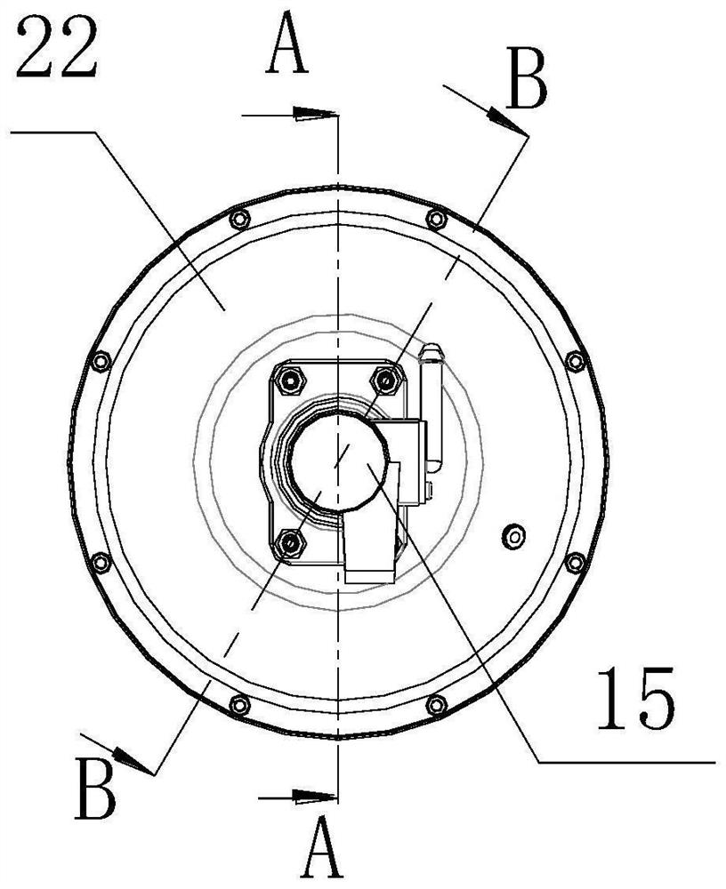
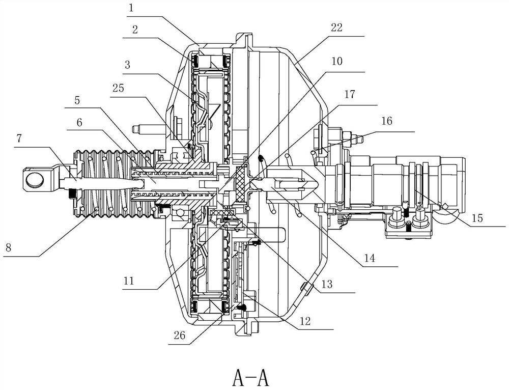
[0037] Such as Figure 1 to Figure 4 As shown, an electronically controlled brake booster for use in a vehicle braking system according to an embodiment of the present invention includes a housing, which may be made of any suitable material, for example, stamped from sheet metal like a conventional vacuum booster production. The shell is composed of two parts, the front shell 1 and the rear shell 22, and the front shell 1 and the rear shell 22 are connected and fastened by suitable fixing devices to form a whole. Preferably, the front shell 1 and the rear shell 22 are coaxial shell structures with a circular cross-section having approximately the same radius, and the two are connected by bolts.

[0038] The shell can be mounted to the vehicle body by suitable fixtures or structures. A motor is fixedly installed in the front housing 1, and the motor is composed of a stator 2 and a rotor 3, wherein the stator 2 is fixedly installed on the inner peripheral wall of the front hou...

Embodiment 2

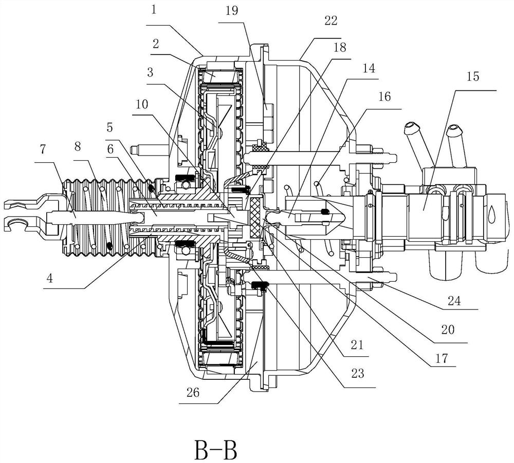
[0055] Such as Figure 5 to Figure 7 As shown, in this embodiment, the rotor 3 is rotatably coaxially installed in the front housing 1 through the bearing seat, and the rotor 3 is coaxially fixed with a nut sleeve 4, and the rotor 3 is non-rotatably fixed with the nut sleeve 4 through the connecting arm. connect. When the rotor 3 rotates, the nut sleeve 4 rotates synchronously with the rotor 3 .

[0056] The nut sleeve 4 is provided with a screw rod 5 that can rotate relative to the nut sleeve 4 , and the screw rod 5 and the nut sleeve 4 are arranged coaxially. In the initial state, one end of the screw rod 5 is threadedly connected with the nut sleeve 4 , and the other end protrudes from the front casing 1 in the axial direction and extends outward. The end of the screw rod 5 near the brake master cylinder 15 is fixedly equipped with a positioning support frame 23, and the positioning support frame 23 is sleeved and installed on the support rod 24 on the rear housing 22. Th...

Embodiment 3

[0063] The present application also discloses a vehicle equipped with the electronic brake booster disclosed in the above embodiments, and the booster is installed in a structure where the front of the vehicle is close to the chassis.

[0064] For family cars, it can replace the position of the original electronic brake booster, so that the original installation space has more space for luggage. For flat-top trucks using vacuum boosters, they can be installed in the original position where the vacuum booster was installed, and do not require accessories such as vacuum pumps, which greatly reduces the installation space and reduces the weight of the vehicle.


PUM


Abstract

The invention discloses an electronic brake booster. The electronic brake booster comprises a push rod, a motor and a circumferential rotating axial translation device, the push rod transmits operating force to a brake master cylinder and can move axially, the circumferential rotating axial translation device is connected with a motor rotor in a matched mode, and circumferential rotation of the motor rotor is converted into axial movement of the circumferential rotating axial translation device. The electronic brake booster is characterized by further comprises a shell and a control panel assembly, the control panel assembly comprises a control panel, the control panel is arranged in the shell, and the control panel is connected with a vehicle electrical system. According to the electronic brake booster, the size of the whole brake booster system is reduced, the installation process is simplified, the installation cost is reduced, and the control precision is improved.

Description

technical field [0001] The invention belongs to the technical field of brake devices, and in particular relates to an electronic brake booster. Background technique [0002] At present, the electric power-assisted braking system controls the brake booster electronically, and the electronic control device is controlled by the electronic control system of the vehicle, or the brake booster is controlled by an external control unit to complete the control of the motor. If it is connected to the electronic control system of the vehicle for installation, then when the brake booster fails, it is necessary to re-connect the electronic control system of the vehicle itself to complete the maintenance and installation. At the same time, the external control unit will increase the volume, resulting in the entire electric The volume of the booster system is large, which is not conducive to the rational use of vehicle space and weight reduction. At the same time, the external control unit...

Claims


Application Information

Patent Timeline
Patent Type & Authority Applications(China)
IPC IPC(8): B60T13/74
CPCB60T13/745
Inventor 蔡清理温正荣李显彰陈奎
Owner ZHEJIANG SANXING MECHANICAL & ELECTRONICSAL STOCK
Why Eureka
Try Eureka