Pin type continuous lifting system for wind power platform

A lifting system and pin-type technology, applied in construction, artificial island, infrastructure engineering, etc., can solve the problems of hidden safety hazards, difficult to advance, and the pin is difficult to align with the pin hole, etc., to protect the oil cylinder, use safety, and avoid corrosion. Effect

Active Publication Date: 2021-11-26
南通中舟风电工程技术有限公司
View PDF1 Cites 0 Cited by
  • Summary
  • Abstract
  • Description
  • Claims
  • Application Information

AI Technical Summary

Problems solved by technology

[0003] However, there are still obvious defects in its use: 1. The above-mentioned device cannot realize continuous lifting, so its lifting efficiency is low and it is inconvenient to use; 2. The plug-type continuous lifting system for wind power platforms is often used In seaside, riverside and other working conditions, the plug is vulnerable to sea wind erosion. If the plug is not found in time after being eroded, it will make it difficult for the plug to align with the plug hole, which will make it difficult to push and cause damage to the oil cylinder. Security risks

Method used


Image

  • Pin type continuous lifting system for wind power platform
  • Pin type continuous lifting system for wind power platform
  • Pin type continuous lifting system for wind power platform

Examples


Embodiment

[0029] see Figure 1 to Figure 5 , the present invention provides a technical solution:

[0030] A plug-type continuous lifting system for a wind power platform, comprising:

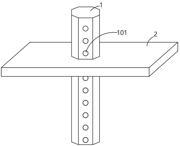
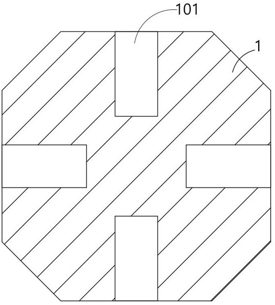
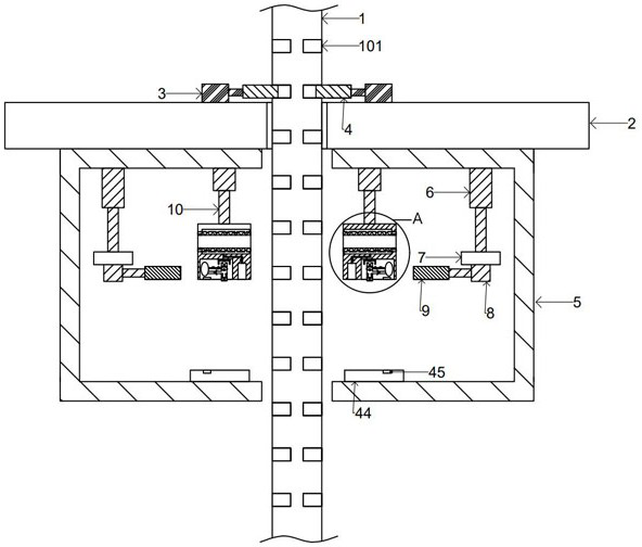
[0031] For the legs, the four sides of the legs 1 are equidistantly provided with pin holes 101, the legs 1 move through the platform 2, and can rise or fall relative to the platform 2;

[0032] The first oil cylinder 3, the first oil cylinder 3 is horizontally arranged on the top surface of the platform 2, the output end of the first oil cylinder 3 is fixedly provided with the first pin 4, and the cross-sectional shape and size of the first pin 4 and the pin hole 101 are exactly the same, Therefore, when the first pin 4 is inserted into the pin hole 101, it can fully contact with the top wall and the bottom wall of the pin hole 101, so as to avoid the automatic decline of the pile leg 1 under its own gravity due to the existence of a gap, and then the movement deviation occurs;

[0033] The frame plat...

Embodiment 1

[0041] When in use, since the device is provided with four second plugs 9, the second plugs 9 in opposite positions can be returned to one group, so the four second plugs 9 can be divided into two groups.

[0042] In the initial state, the two sets of second pins 9 are all inserted into the pin holes 101 of the legs 1, and are located at the same height:

[0043] Step 1, the third oil cylinder 8 retracts, so that the first group of second latches 9 move out of the latch holes 101;

[0044] Step 2: start the second oil cylinder 6, so that the second group of second pins 9 extend downward by a unit distance, causing the leg 1 to move downward relative to the platform 2, and at this time, the first group of second pins 9 remains motionless, After the movement, the first set of second pins 9 is aligned with the last pin hole 101;

[0045] Step 3, extend the third oil cylinder 8, so that the first group of second latches 9 are inserted into the flush latch holes 101 in the above s...

Embodiment 2

[0050] When the second latch 9 is moving, it will be limited by the operation block 11 and the baffle plate 44. When the second latch 9 pushes the lower push plate 29 upward, the lower push plate 29 will drive the lower plate through the second connecting block 28. 27, so that the sliding plate 27 is pressed upwards to the push-type counter 25, thereby realizing counting, and then counting the number of times that the second latch 9 moves up, so as to facilitate the measurement of the total distance of the platform 2 for reference; at the same time, when pushing down During the upward movement of the plate 29, the lower plate 27 squeezes the gas in the cavity of the hollow tube 23 into the upper slide plate 36, and then pushes the upper slide plate 36 upwards, and the lower push plate 29 loses the thrust and is under the influence of its own gravity and the elastic force of the spring 26. When falling under the action, the gas in the air bag 31 will enter the hollow tube 23 thr...


PUM


Abstract

The invention provides a bolt-type continuous lifting system for a wind power platform. The four sides of the legs are equidistantly provided with bolt holes, and the legs move through the platform; there are four installation frame plates fixedly arranged on On the bottom surface of the platform, a second oil cylinder is longitudinally arranged on the side of the installation frame plate close to the platform, and a second pin is fixedly arranged at the output end of the third oil cylinder; a water-absorbing pad is fixedly arranged in the through groove, and The side of the empty pipe communicates with the airbag through the intake pipe, and a switch is correspondingly provided on the side of the bearing plate close to the trigger lever. The invention provides a pin-type continuous lifting system for wind power platforms, which can realize continuous lifting of the legs, and after the second pin is used for a certain number of times, it will automatically trigger the corresponding device to apply protective liquid to the second pin. It is prevented from being corroded by the sea breeze, so that the second pin can be accurately inserted into the pin hole, effectively protecting the oil cylinder and making it safer to use.

Description

technical field [0001] The invention relates to the technical field of lifting equipment, in particular to a plug-type continuous lifting system for wind power platforms. Background technique [0002] In the prior art, the application number is "201711192256.7", a self-elevating platform hydraulic bolt lifting device, including: a bolt lifting device, the bolt lifting device is equipped with a pile frame, a set of balance components, a fixed ring beam, and a moving ring beam , a group of hydraulic lifting cylinders, at least one set of bolt devices, height detection devices and control devices, the fixed ring beam is connected to the pile frame through the balance component, the lug plate at the end of the hydraulic lifting cylinder is hinged to the fixed ring beam, and the piston The lug plate at the end of the rod is hinged with the moving ring beam. Both the fixed ring beam and the moving ring beam are equipped with bolt devices. The fixed ring beam and the moving ring be...

Claims


Application Information

Patent Timeline
Patent Type & Authority Patents(China)
IPC IPC(8): E02B17/08
CPCE02B17/08E02B17/0809E02B17/0872
Inventor 季刚
Owner 南通中舟风电工程技术有限公司
Why Eureka
Try Eureka