Selective water plugging method for high-water-content oil well of bottom water reservoir

A bottom water reservoir, selective technology, applied in chemical instruments and methods, earthwork drilling and production, wellbore/well components, etc., can solve the problems of difficult water shutoff and poor water shutoff effect in edge and bottom water reservoirs, and achieve Effects of increasing stability and strength, increasing oil resistance, and strengthening the effect of pressing the cone

Active Publication Date: 2021-10-01
SOUTHWEST PETROLEUM UNIV
13 Cites 2 Cited by

AI-Extracted Technical Summary

Problems solved by technology

[0005] The purpose of the present invention is to provide a selective water shutoff method for high water content oil wells in bottom wat...

Method used

At last, use polymer solution to carry out over-displacement, and over-displacement will also replace the water-blocking agent to a certain position in the near-well zone, so as to ensure that there is a certain liquid production capacity after the plugging, prevent the water injection well injection pressure from being too high, and prolong the plugging The expiry date of the water solution.
In summary, the water shutoff method of the present invention is to inject the mixed solution of foaming agent, macromolecular solution, foam stabilizer and crosslinking agent after injecting nitrogen pressure cone in the wellbore, forming gel in the formation Foam. Then, the foam in the high-permeability layer is cleaned by flowback t...

Abstract

The invention discloses a selective water plugging method for a high-water-content oil well of a bottom water reservoir. The selective water plugging method comprises the following steps of injecting a nitrogen pressure cone into a shaft, injecting a mixed solution of a foaming agent, a polymer solution, a foam stabilizer and a cross-linking agent, and forming gel foam in a stratum. then removing foam in a high-permeability layer through flowback, so that the purposes of temporary plugging of low permeability and enabling a subsequent water plugging agent to directionally enter the high-permeability layer are achieved; then injecting the water plugging agent, and enabling the water plugging agent to build an artificial partition plate at the proper position in a water producing layer, so that bottom water is prevented from moving upwards, and bottom water coning is restrained; and finally, enabling the water plugging agent to be displaced out of a certain position of a near wellbore zone through over-displacement of a polymer solution, so that a certain liquid production capacity after plugging is ensured, the injection pressure of the water injection well is prevented from being too high, and the validity period of the water plugging agent is prolonged. Under the combined action of the steps, directional water plugging is achieved, and the problems that water breakthrough of the oil well is too early, and the yield is sharply reduced after water breakthrough are solved.

Application Domain

Technology Topic

Image

  • Selective water plugging method for high-water-content oil well of bottom water reservoir
  • Selective water plugging method for high-water-content oil well of bottom water reservoir
  • Selective water plugging method for high-water-content oil well of bottom water reservoir

Examples

  • Experimental program(2)

Example Embodiment

[0034] Example 1
[0035] The selective water shutoff method of the high water-cut oil well in the bottom water reservoir of the present invention is specifically as follows:
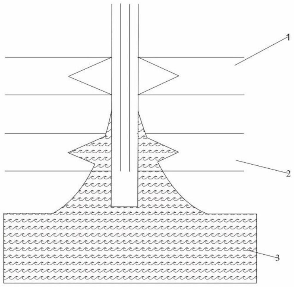
[0036] like figure 1 As shown, with long-term water injection production, the oil well enters the stage of high water cut, and the bottom water invades seriously, resulting in water cones and water flooding in the lower high permeability layer.
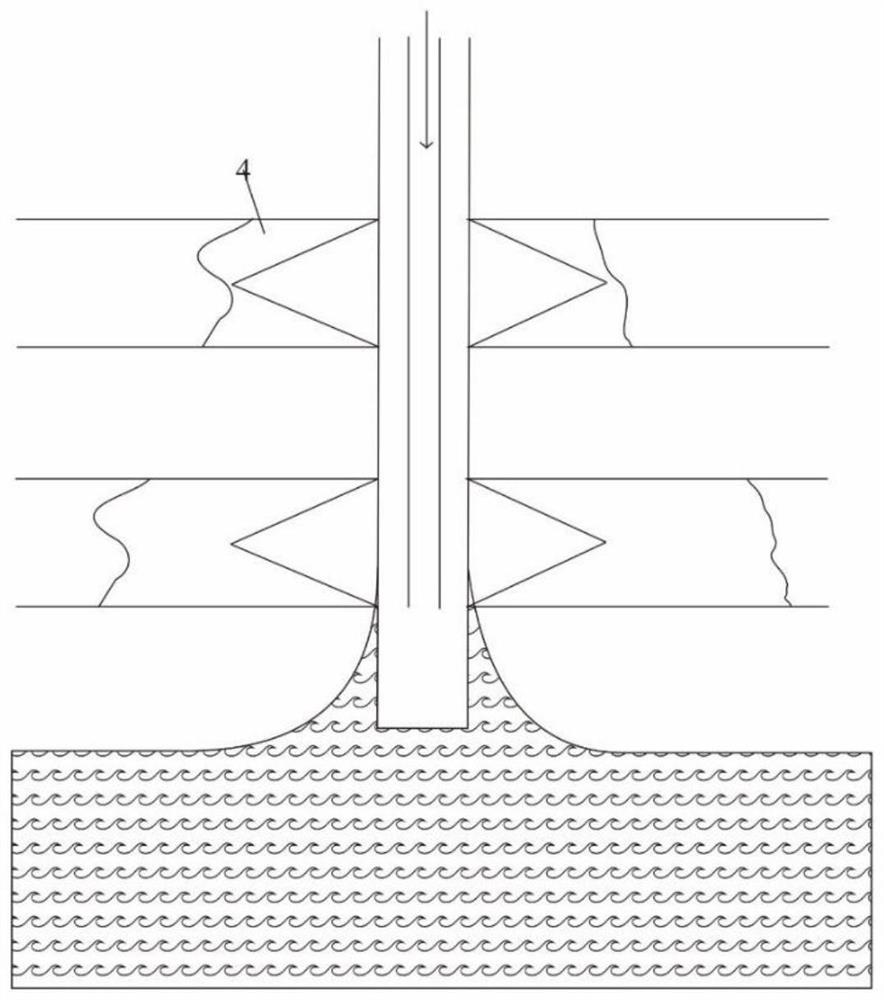
[0037] At this time, if figure 2 As shown, nitrogen is injected downhole at high speed and high pressure through tubing. At this time, nitrogen preferentially enters the hyperpermeable layer to increase the pressure of the hyperpermeable layer. The intrusion of nitrogen drives the intrusive water to the lower part to achieve the purpose of pressing down the water cone, which can be used for subsequent plugging. The entry of water agent creates conditions. Since nitrogen is injected into the formation at high speed and high pressure, some nitrogen enters the low-permeability layer, and this part of nitrogen further increases the intralayer pressure of the low-permeability layer itself. Compared with the high-permeability layer, the pressure conduction of the low-permeability layer is slower per unit time, and the pressure drop rate is slower, which leads to the gradual increase of the pressure difference between the high- and low-permeability layers after gas injection, which makes the subsequent water plugging Under a certain injection pressure, the agent can enter the high-permeability water-producing layer directionally.
[0038] Then inject the mixed solution (mixed solution of foaming agent, polymer solution, foam stabilizer and crosslinking agent) downhole at high speed, such as image 3 shown. After the foaming agent enters the formation, it mixes with the nitrogen injected from the previous plug to form a gel foam in the porous medium. After the foam is formed in the hyperpermeable layer, the density of the foaming agent and the foam itself is greater than that of nitrogen, which can further strengthen the nitrogen pressure. cone effect. At the same time, due to the formation of foam in the high-permeability layer, which reduces its own permeability, the mixed solution begins to enter the low-permeability layer, and mixes with nitrogen in the low-permeability layer to generate foam, which produces temporary plugging protection for the low-permeability layer. Preferably, the polymer solution may be 0.3%-0.4% HPAM solution. The foaming agent is fatty alcohol ether sulfate sodium salt (AES). The foam stabilizer is a hydrophobically modified nano-SiO modified with N,N-dimethylferrocenyl hexadecylmethylammonium bromide (Fc16AB). 2 particles. The crosslinking agent is a composite crosslinking system (organic chromium: phenolic resin = 3:5). The cross-linking time of the composite cross-linking agent and polyacrylamide is shorter than the half-life of the foam formed by the foaming agent and gas, ensuring that the cross-linking agent and polyacrylamide can undergo cross-linking reaction when only a small amount of foam is broken.
[0039] After injecting a certain amount of mixed solution, replace the oil nozzle with a small production pressure difference, and open the well for 3-8 hours for production, such as Figure 4 shown. Both the high-permeability layer and the low-permeability layer tend to be produced during flowback, and the fluid in the formation flows toward the wellbore. Since the viscosity of nitrogen gas is much smaller than that of the mixed solution and the gel foam produced, nitrogen migration is easier. Move from a little distance away from the wellbore to the vicinity of the wellbore and further fully mix with foaming agent and other solutions to improve the quality of foam generation and strengthen the effect of temporary plugging and cone pressure; During production with low production pressure difference, the foam in the high-permeability layer will flow back preferentially, and the pressure in the high-permeability layer will decrease, which will increase the pressure difference between the low-permeability layer and the high-permeability layer, which is beneficial for the subsequent water shutoff agent to enter the high Seepage layer.
[0040] like Figure 5 As shown, after the above steps, the water blocking agent is injected into the formation to establish an artificial partition, and the water blocking agent enters the water-producing layer in a directional manner to realize intelligent and selective water blocking. The screening conditions of the water blocking agent are as follows:
[0041] (1) It is an integral water blocking agent, that is, the blocking agent is solidified or gelled as a whole.
[0042] (2) The water blocking agent used is preferably in the form of molecular or ion dispersion, and the reaction time should be long enough.
[0043] (3) The water blocking agent should be combined, and the strength of the blocking agent should be as high as possible.
[0044] (4) The water shutoff agent used near the well must ensure no production under large production pressure difference.
[0045] (5) The configuration and construction of the water blocking agent should be simple and easy to operate, and the construction risk is small.
[0046] (6) The cost of the water blocking agent is low and the source is wide.
[0047] (7) The plugging agent for establishing the partition can use weak water blocking agent in the far well, and use high strength water blocking agent in the near well.
[0048] The amount of water blocking agent can be calculated as follows:
[0049] q=π(2r) 2 hφ
[0050] In the formula: q-total dosage of blocking agent, m 3; r-plugging radius, m; φ-reservoir porosity, %; h-separator thickness, m.
[0051] Finally, polymer solution is used for over-displacement, which also displaces the water-blocking agent from a certain position near the wellbore to ensure a certain liquid production capacity after plugging, prevent the injection pressure of the water injection well from being too high, and prolong the life of the water-blocking agent. expiration date.
[0052] Under the combined action of the above steps, intelligent selective water shutoff of high water cut oil wells in bottom water reservoirs can be realized, and the problem of sharp decline in production after water breakthrough in oil wells can be solved.

Example Embodiment

[0053] Example 2
[0054] The water shutoff method of the present invention is applied to a specific high water cut oil well in a certain bottom water reservoir. The specific method is as follows:
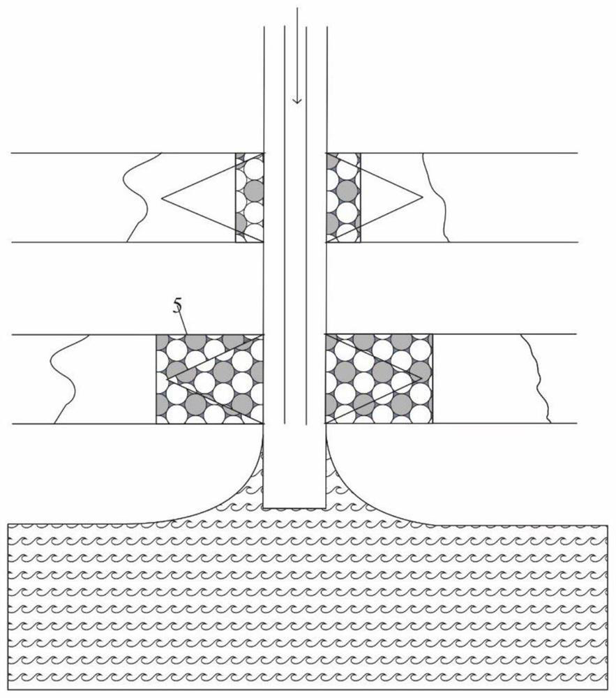
[0055] S1. Inject nitrogen gas into the well at high speed and high pressure, so that nitrogen gas enters the high-permeability water-producing layer. The entry of nitrogen gas drives the intrusive water to the lower part, achieving the purpose of pressing down the water cone and providing conditions for subsequent operations. According to the research of the gel foam system, the optimal amount of nitrogen gas is twice the volume of the mixed solution injected in step S2, and the volume calculation formula of the mixed solution is: Q=πR 2 hφ, where R=10m, h=2m, φ=0.3. The amount of nitrogen injected uses the state equation PV=nRT to convert the ground volume, and the gas injection speed is controlled at 600-900m 3 /h, the gas injection pressure is higher than the formation pressure.
[0056] S2. Inject a mixed solution of foaming agent, HPAM, cross-linking agent and foam stabilizer into the well, wherein the foaming agent is fatty alcohol ether sulfate sodium salt with a mass concentration of 1%; the mass concentration of HPAM is 0.3%-0.4% ; The cross-linking agent is a composite cross-linking system (organic chromium: phenolic resin = 3:5). The cross-linking time of the composite cross-linking agent and polyacrylamide is less than the half-life of the foam formed by the foaming agent and gas, so that the cross-linking agent can react with polyacrylamide when only a small amount of foam is broken, and the mass concentration is 0.1%; the foam stabilizer is hydrophobically modified nano-SiO modified with N,N-dimethylferrocenyl hexadecyl methylammonium bromide (Fc16AB) 2 Particles, the mass concentration is 0.1%. The injection volume of the mixed solution is calculated by the formula in step S1, and the injection volume is about 188.4m 3.
[0057] S3. After the injection of the mixed solution is completed, change the oil nozzle to a production pressure difference slightly greater than the start-up pressure difference of the hyperpermeable layer, and open the well for 3-8 hours to fully mix the nitrogen in the formation with the foaming agent, and discharge the hyperpermeable Inner foam.
[0058] S4. After completing the above steps, inject the water shutoff agent into the partition, and the water shutoff agent adopts the temperature-resistant, salt-resistant and high-temperature self-crosslinking in-situ polymerized water shutoff gel in the patent CN104449618B. The dosage of water shutoff agent adopts the formula q=π(2r) 2 Calculation of hφ, where r=10m, h=2m, φ=0.3, injection volume is about 753.6m 3. Since the low-permeability layer is temporarily plugged, after the plugging agent is injected into the formation, it will only enter the high-permeability layer and extend laterally in the high-permeability layer to establish an artificial partition at a suitable position. The breakthrough pressure gradient of the plugging agent in the core is greater than 9MPa/m, and the plugging rate reaches 99%.
[0059] S5. Use HPAM polymer solution for over-displacement. The viscosity of the over-displacement fluid is greater than that of the displaced fluid. Over-displacement will also displace the plugging agent from a certain position near the wellbore to ensure a certain fluid production capacity after plugging and prevent water injection wells. The injection pressure is too high and the validity period of the water shutoff agent is extended.
[0060] Using the above-mentioned technology, the water content of the well is reduced by 18.9%, and the water plugging effect is good.
[0061] In summary, the water plugging method of the present invention is to inject a mixed solution of foaming agent, polymer solution, foam stabilizer and crosslinking agent after injecting nitrogen pressure cone into the wellbore to form gel foam in the formation. Then, the foam in the high-permeability layer is cleaned by flowback to achieve the purpose of temporary plugging and low-permeability, so that the subsequent water shutoff agent can enter the high-permeability layer in a directional manner. Next, water shutoff agent is injected, and the water shutoff agent establishes artificial partitions at appropriate positions in the water-producing layer to prevent bottom water from escaping and inhibit bottom water coning. Finally, through polymer solution over-displacement, the water blocking agent is displaced from a certain position near the wellbore to ensure a certain liquid production capacity after plugging, prevent the injection pressure of the water injection well from being too high, and prolong the validity period of the water blocking agent.

PUM

no PUM

Description & Claims & Application Information

We can also present the details of the Description, Claims and Application information to help users get a comprehensive understanding of the technical details of the patent, such as background art, summary of invention, brief description of drawings, description of embodiments, and other original content. On the other hand, users can also determine the specific scope of protection of the technology through the list of claims; as well as understand the changes in the life cycle of the technology with the presentation of the patent timeline. Login to view more.

Similar technology patents

Classification and recommendation of technical efficacy words

Why Eureka
Try Eureka