Deep groove ball bearing with split type retainer

A deep groove ball bearing and cage technology, applied in the field of bearings, can solve the problems of cage melting and cracking, unfavorable production and processing efficiency, and inconvenient assembly

Active Publication Date: 2021-10-01
C&U CO LTD
View PDF13 Cites 1 Cited by
  • Summary
  • Abstract
  • Description
  • Claims
  • Application Information

AI Technical Summary

Problems solved by technology

However, during use, under high-speed conditions of rapid acceleration or deceleration, a high temperature rise is likely to occur, causing the cage to melt and crack, and the cage is prone to impact fracture in the pocket or other positions, and attention should be paid to maintenance The lubricating state of the cage balls should be replenished in time, but the existing cages are difficult to replenish oil, and the assembly is also very inconvenient, which reduces the overall use effect of the cage and is not conducive to improving production and processing efficiency.

Method used


Image

  • Deep groove ball bearing with split type retainer
  • Deep groove ball bearing with split type retainer
  • Deep groove ball bearing with split type retainer

Examples


Embodiment Construction

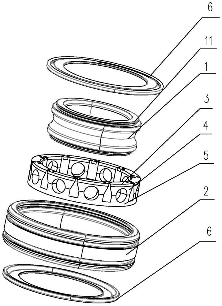
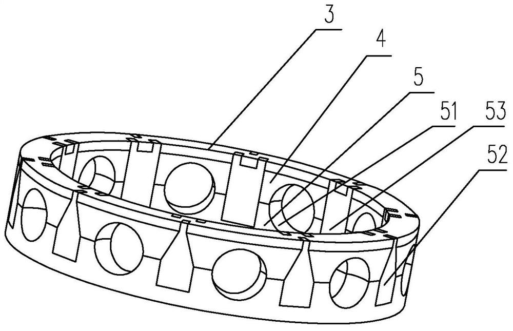
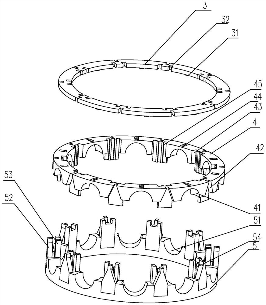
[0029] The first embodiment of the deep groove ball bearing with split cage of the present invention is as Figure 1 to Figure 3 As shown: including outer ring 2, inner ring 1, cage and steel balls, the cage is set between the outer ring 2 and the inner ring 1, and the cage is separated to form an upper frame body 3, a bearing frame 4 and The lower frame body 5 is provided with pockets 41 for accommodating steel balls at intervals on the carrier frame 4, and a connecting platform is arranged between adjacent pocket grooves 41 on the carrier frame 4, and a connecting platform is formed on the outer wall of the connecting platform. There is a first insertion groove 42, a second insertion groove 43 is provided on the inner wall of the connection platform, a connection groove 44 is opened on the bottom surface of the pocket groove 41, an oil storage chamber is formed on the upper frame body 3, and the storage chamber The opening of the oil chamber is set toward the connecting groo...


PUM


Abstract

The invention discloses a deep groove ball bearing with a split type retainer. The deep groove ball bearing comprises an outer ring, an inner ring, a steel ball, an upper frame body, a bearing frame and a lower frame body, the bearing frame is provided with pocket grooves, a connecting table is arranged on the bearing frame, first inserting grooves and second inserting grooves are formed in the two side walls of the connecting table, connecting grooves are formed in the bottom face of the pocket grooves, and an oil storage cavity is formed in the upper frame body. Positioning flanges are formed in an opening of the oil storage cavity, the positioning flanges are matched with the connecting grooves in an inserting mode, arc-shaped grooves are formed in the positions, corresponding to the pocket grooves, of the lower frame body, connecting bases are formed on the lower frame body, first inserting blocks and second inserting blocks are arranged on the connecting bases, the first inserting blocks are matched with the first inserting grooves in an inserting mode, and the second inserting blocks are matched with the second inserting grooves in an inserting mode. Positioning blocks are arranged at the ends of the first inserting blocks and the second inserting blocks, positioning holes used for being connected with the positioning blocks in an inserted mode are formed in the upper frame body. The overall structure is convenient to install and higher in stability, and the using effect and the production and machining efficiency of the overall structure are improved.

Description

technical field [0001] The invention relates to the technical field of bearings, in particular to a deep groove ball bearing with a split cage. Background technique [0002] A deep groove ball bearing is usually equipped with a cage, which is usually assembled between the raceways of the inner ring and the outer ring. The cage usually has a ring-shaped main structure and ball pocket holes evenly distributed along the circumference. The ball pocket hole usually adopts a concave spherical surface similar to the rolling element of the ball bearing and has a slightly larger curvature radius, and is opened on the inner diameter surface and the outer diameter surface of the cage body. However, during use, under high-speed conditions of rapid acceleration or deceleration, a high temperature rise is likely to occur, causing the cage to melt and crack, and the cage is prone to impact fracture in the pocket or other positions, and attention should be paid to maintenance To ensure the...

Claims


Application Information

Patent Timeline
Patent Type & Authority Applications(China)
IPC IPC(8): F16C33/38F16C33/44F16C33/66F16C33/58F16C33/78F16C37/00F16C19/16
CPCF16C33/3881F16C33/44F16C33/664F16C33/6648F16C33/583F16C33/7806F16C33/783F16C37/007F16C19/16F16C2380/26F16C2226/70F16C2208/04F16C2208/62F16C2208/36F16C19/06F16C33/6651F16C33/78
Inventor 白雪峰徐家良
Owner C&U CO LTD
Why Eureka
Try Eureka