Mine underground downward drift two-step stoping controlled blasting method

A technology for controlling blasting and mines, which is applied in blasting, ground mining, earthwork drilling and mining, etc. It can solve problems such as unreasonable design of the distance between the top hole, the auxiliary hole and the filling body, the difficulty in accurately controlling the blasting time of the blast hole, and the impact on the blasting effect. , to achieve the effect of improving the blasting effect of the section, good cutting effect, and accurate blasting interval time

Inactive Publication Date: 2021-10-01
嵩县山金矿业有限公司
View PDF6 Cites 0 Cited by
  • Summary
  • Abstract
  • Description
  • Claims
  • Application Information

AI Technical Summary

Problems solved by technology

[0004] In view of the fact that the existing rock drilling rigs are difficult to drill wedge-shaped holes when the cross section is small, vertical cutting holes are often used underground, and the cutting space is relatively narrow, and it is difficult to throw rocks out. It is reasonable and seriously affects the blasting effect. Smooth surface blasting is rarely used in the top hole and the side hole. The commonly used millisecond delay detonator detonator is difficult to accurately control the blasting time of the blast hole and other technical problems. Two-step recovery control blasting method

Method used


Image

  • Mine underground downward drift two-step stoping controlled blasting method
  • Mine underground downward drift two-step stoping controlled blasting method
  • Mine underground downward drift two-step stoping controlled blasting method

Examples


Embodiment

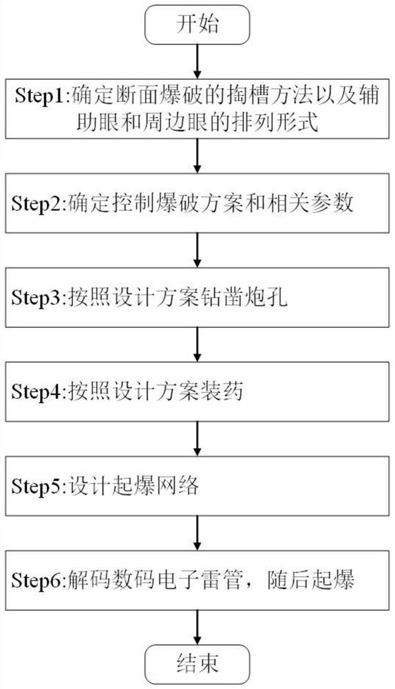
[0043] In this example, the surrounding rocks belong to grades II-III, with relatively good lithology, relatively difficult to blast, and a slightly arched section of 4×4m.

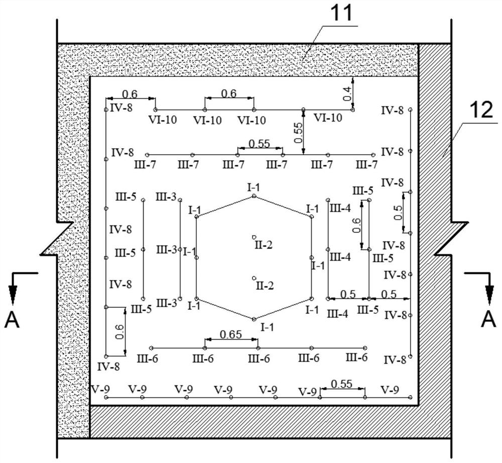
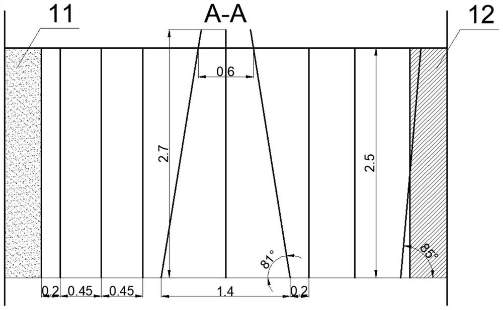
[0044] As a specific example, figure 2 Shown is the front view of the borehole design for the two-step recovery control blasting of the downhole approach. Among them, Ⅰ is the circular cutting hole, Ⅱ is the cutting hole, Ⅲ is the auxiliary hole, Ⅳ is the side hole, Ⅴ is the bottom hole, and Ⅵ is the top hole; the numbers 1 to 10 are the exposure sequence of the blast hole; the number 11 is Filling body, number 12 is surrounding rock. Firstly, a rock drilling rig is used to drill a hollow hole in the center of the section, and then a ring-shaped hole is drilled based on this. The vertical hole spacing is 0.5m, and the horizontal hole spacing is 1.4m. The super-deep slot hole is 0.2m, and the depth of the super-deep blast hole is 2.7m. Then, it is 0.1m away from the surrounding rock, and the auxiliary ...


PUM


Abstract

The invention discloses a mine underground downward drift two-step stoping controlled blasting method. The mine underground downward drift two-step stoping controlled blasting method comprises the following steps of: (1) determining a cutting method for section blasting and an arrangement form of auxiliary holes and peripheral holes; (2) determining a controlled blasting scheme and related parameters; (3) drilling blast holes according to the design scheme; (4) charging explosives into the blast holes: the charging coefficient of an annular cut hole is 0.9, the charging coefficient of a bottom hole is the same as that of the annular cut hole, 1-2 cartridges of explosives are charged in a cut empty hole, the charging coefficient of the auxiliary hole is 0.7, the charging density of a peripheral hole line is 0.3 kg / m, charging is conducted in a smooth blasting mode, and all the blast holes need to be blocked by water stemming; (5) detonating the network: detonating the cut holes and the auxiliary holes by adopting electronic detonators, detonating the peripheral holes by adopting detonating cords, and performing triangular lapping on the detonating cords; and (6) decoding digital electronic detonator, and then detonating. The mine underground downward drift two-step stoping controlled blasting method disclosed by the invention has the advantages that the cutting effect is good, the drilling depth is large, the blasting section is regular, filling bodies at the upper part and the edge part of the section can be protected, the blasting cost is low and so on.

Description

technical field [0001] The invention belongs to the field of rock drilling controlled blasting in underground mines, and in particular relates to a two-step recovery controlled blasting method for a downward approach in a mine. Background technique [0002] With the development of national science and technology, mine mining has gradually moved towards mechanization and automation, which has greatly improved mine production efficiency. At present, many mines have introduced rock drilling rigs for mining, which can move freely and have high flexibility. Compared with the previous drilling methods, the operating efficiency has been improved and the operating environment has been improved. However, due to the large volume of the rock drilling rig, it is difficult to drill wedge-shaped holes when the excavation section is small, resulting in poor cutting effect during blasting. In recent years, as a highly efficient, low-cost, and high-efficiency mining method, the downward app...

Claims


Application Information

Patent Timeline
IPC IPC(8): F42D1/00F42D1/08F42D3/04E21C41/16
CPCF42D1/00F42D1/08F42D3/04E21C41/16
Inventor 刘吉兴马章印于曙华彭康郎晓东刘青灵邱洋洋薛超郭宏扬张亚鹏
Owner 嵩县山金矿业有限公司
Why Eureka
Try Eureka