A method for correcting non-linear errors in fringe projection 3D measurement
A nonlinear error, three-dimensional measurement technology, applied in the field of three-dimensional measurement, can solve the problems of phase distribution periodic error, large amount of calculation, phase shift fringe image distortion, etc., to reduce nonlinear error, high measurement flexibility, and measurement speed. quick effect
- Summary
- Abstract
- Description
- Claims
- Application Information
AI Technical Summary
Problems solved by technology
Method used
Image


Examples
Embodiment 1
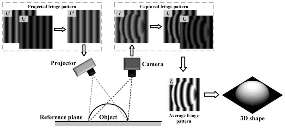
[0064] Step S1: Build a fringe projection three-dimensional measurement system, including a projector and a camera, the projector and the camera are triggered to start working synchronously, and the projector, the camera and the measured object form a triangulation relationship; figure 1 The principle diagram of nonlinear error correction in fringe projection 3D measurement is shown;
[0065] Step S2: The projector projects three color stripe patterns in sequence To the surface of the measured object, where the color stripe pattern The red channel encodes the cosine fringes of Blue channel encodes sinusoidal stripes The green channel does not encode any information and is directly set to zero; figure 2 (a) shows the colorful stripe pattern figure 2 (b) shows the red channel encoded cosine fringes figure 2 (c) shows the blue channel encoding sinusoidal fringes
[0066] Step S3: The camera collects the modulated color fringe image of the measured object; assum...
Embodiment 2
[0070] Step S1: Build a fringe projection three-dimensional measurement system, including a projector and a camera, the projector and the camera are triggered to start working synchronously, and the projector, the camera and the measured object form a triangulation relationship; figure 1 The principle diagram of nonlinear error correction in fringe projection 3D measurement is shown;
[0071] Step S2: The projector projects three color stripe patterns in sequence to the surface of the measured object; Figure 4 (a) shows the image of the object under test.
[0072] Step S3: The camera collects the modulated color fringe image of the measured object; Figure 4 (b) shows the acquired colored fringes I″ n (x,y); Figure 4 (c) shows the red channel stripe I″ n,r (x,y); Figure 4 (d) shows the blue channel stripe I″ n,b (x,y);
[0073] Step S4: By setting the weighting coefficient Calculate the red channel stripe I″ n,r (x,y) and blue channel stripe I″ n,b (x,y) weight...
PUM
 Abstract
Description
Claims
Application Information