
Liquid cooling busbar

A busbar and liquid-cooled technology, which is applied in the direction of using liquid cooling for modification, cooling/ventilation/heating transformation, root rod/rod/wire/strip conductor, etc., can solve the problem of poor heat dissipation, small contact area of ​​cooling medium, and restricted and other issues to achieve the effect of ensuring cooling effect, good cooling effect and reducing manufacturing cost

Pending Publication Date: 2021-10-01
阳光氢能科技有限公司
View PDF7 Cites 0 Cited by
  • Summary
  • Abstract
  • Description
  • Claims
  • Application Information

AI Technical Summary

Problems solved by technology

However, when multi-layer busbars are arranged in parallel and the spacing is small, it is difficult for the existing air-cooled heat dissipation method to dissipate heat to the part between two adjacent busbars, and with the increase of the busbar length, the heat dissipation effect is more Poor; the existing liquid cooling heat dissipation mainly adopts the method of drilling cooling holes on the busbar, and then passing cooling medium into the cooling hole to dissipate heat from the busbar. The diameter of the cooling hole is limited by the cross-sectional area of ​​the busbar, and the cooling medium The actual contact area with the busbar is small, and the heat dissipation effect is poor

Method used


Image

  • Liquid cooling busbar
  • Liquid cooling busbar
  • Liquid cooling busbar

Examples


Embodiment 1

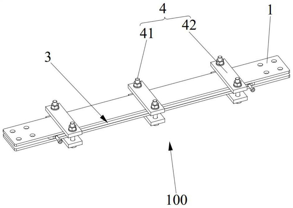
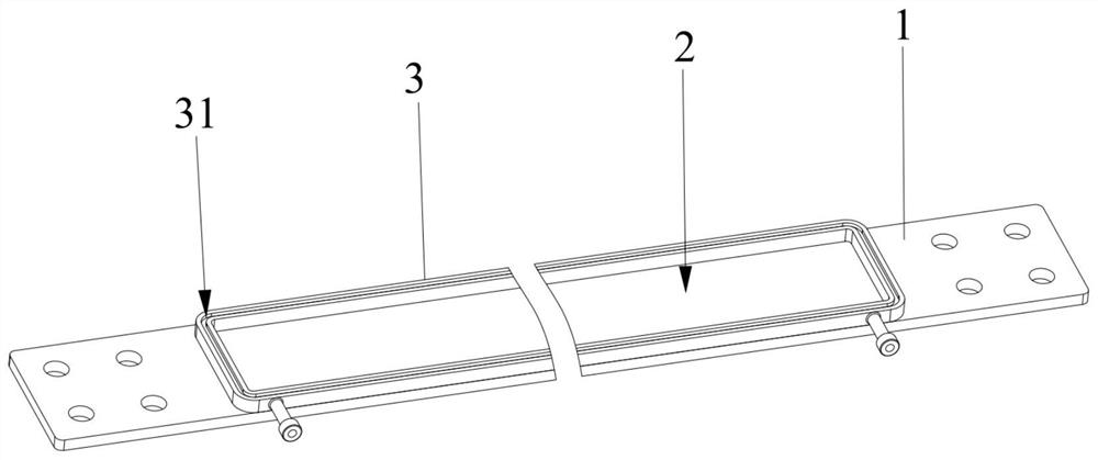
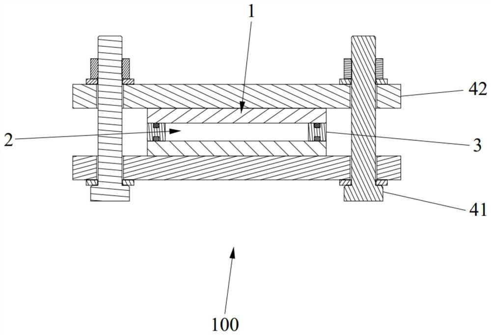
[0035] Such as Figure 1-Figure 4 As shown, this embodiment provides a liquid-cooled busbar 100, the liquid-cooled busbar 100 includes at least two busbar bodies 1, two adjacent busbar bodies 1 are arranged at intervals, and two adjacent busbar bodies 1 can A sealed cooling cavity 2 is formed, and a cooling medium is contained in the cooling cavity 2 . In the liquid-cooled busbar 100, the cooling cavity 2 is formed by two adjacent busbar bodies 1, the busbar body 1 can directly contact the cooling medium, and the direct contact area between the busbar body 1 and the cooling medium is large, and the cooling effect is good. Even if the distance between two adjacent busbar bodies 1 is small or the length of the busbar body 1 is long, the cooling effect of the busbar body 1 can be guaranteed, and the current carrying density of the busbar body 1 can be increased, thereby reducing the The cross-sectional area of ​​the busbar body 1 reduces the manufacturing cost of the busbar body...

Embodiment 2

[0061] This embodiment provides a liquid-cooled busbar 100 , which is different from Embodiment 1 in that the number of sealing frames 3 between two adjacent busbar bodies 1 is at least two.

[0062] like Figure 5 and Figure 6 As shown, in some working conditions, the potentials of two adjacent busbar bodies 1 are the same, and the connection bar 200 of the equipment to be connected extends between the two adjacent busbar bodies 1, and is connected to the two adjacent busbar bodies 1 respectively. The main body 1 is electrically connected, so as to realize the electrical connection between the connection bar 200 and the liquid cooling bus bar 100 .

[0063] like Figure 7 As shown, in order to avoid the connection bar 200, the number of sealing frames 3 between two adjacent busbar bodies 1 is at least two, and each sealing frame 3 is surrounded by two adjacent busbar bodies 1. Assuming that a cooling cavity 2 is formed, at least two sealing frames 3 are arranged at interv...


PUM


Abstract

The invention relates to the technical field of busbar heat dissipation, and discloses a liquid cooling busbar, which comprises at least two busbar bodies, wherein the two adjacent busbar bodies are arranged in a spaced mode and can form a sealed cooling cavity, and a cooling medium is contained in the cooling cavity. According to the liquid cooling busbar, the busbar body and the cooling medium can be in direct contact, the heat exchange area is large, the cooling effect is good, the cooling effect of the busbar body can be ensured even if the distance between two adjacent busbar bodies is small or the length of the busbar body is long, and the current-carrying density of the busbar body can be improved, so that the cross sectional area of the busbar body is reduced, and the manufacturing cost of the busbar body is reduced.

Description

technical field [0001] The invention relates to the technical field of busbar heat dissipation, in particular to a liquid-cooled busbar. Background technique [0002] With the continuous development of technology, the power of power electronic conversion equipment is getting higher and higher, and the carrying capacity of busbars connecting various electrical devices and electrical equipment is also increasing. For heat dissipation considerations, the design of the busbar often requires a lower current-carrying density. In order to meet the demand for high current, the cross-sectional area of ​​the busbar is often large, requiring a large number of metal conductors, and the cost is high. [0003] In the prior art, air cooling or liquid cooling is usually used to dissipate heat from the busbars, so as to increase the current carrying density of the busbars, thereby reducing the manufacturing cost of the busbars. However, when multi-layer busbars are arranged in parallel and ...

Claims


Application Information

Patent Timeline
Patent Type & Authority Applications(China)
IPC IPC(8): H01B5/02H05K7/20
CPCH01B5/02H05K7/2029
Inventor 龚胜伟江才刘晓晖
Owner 阳光氢能科技有限公司
Learn More