

Satellite antenna transmission mechanism and satellite antenna
A technology of satellite antenna and transmission mechanism, which is applied in the direction of antenna, antenna support/installation device, antenna suitable for movable objects, etc., can solve the damage of transmission mechanism, the frame does not have moisture-proof function, and shorten the service life of satellite antenna and other problems to achieve the effect of preventing the accumulation of water vapor
- Summary
- Abstract
- Description
- Claims
- Application Information
AI Technical Summary
Problems solved by technology
Method used
Image

Examples
Embodiment 1
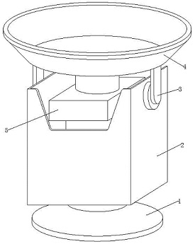
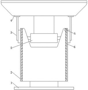
[0035] see Figure 1-4 , in an embodiment of the present invention, a satellite antenna transmission mechanism and a satellite antenna include a fixed bracket assembly 1, a frame 2, a pitch rotation mechanism 3, an antenna assembly 4, and a polarization rotation mechanism 5, and the inside of the vertical inner surface of the frame 2 The positions are up and down vertically, and there are several moisture-proof components 6 that can prevent the accumulation of water vapor for a long time;
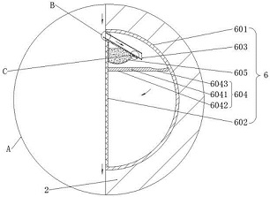
[0036] Each group of moisture-proof components 6 includes an arc plate 601, a metal plate 602, a channel 603, a movable component 604 that can flexibly move according to the entry of water vapor, and a water-absorbing component 605 that can absorb water vapor.
[0037] In the embodiment of the present invention, the appearance of each arc plate 601 is in the shape of a letter C with a right convex semicircle on a longitudinal section;
[0038] Here, the appearance of the arc plate 601 is s...
Embodiment 2
[0046] see image 3 with Figure 5 Compared with Embodiment 1, this embodiment of the present invention differs in that each set of movable components 604 includes a rotating shaft 6041 , a left rotating plate 6042 and a right rotating plate 6043 .
[0047] In the embodiment of the present invention, each rotating shaft 6041 is installed in the upper left position of each cavity in a forward and backward horizontal direction, and a left rotating plate 6042 and a right rotating plate 6043 are fixedly installed on the left and right sides of each rotating shaft 6041, respectively. Each left-turning plate 6042 and right-turning plate 6043 are in a horizontal static equilibrium state under normal conditions, the length of each right-turning plate 6043 is greater than the length of each left-turning plate 6042, and the right end top of each right-turning plate 6043 The positions are all provided with flat grooves, and each right-turning plate 6043 is placed directly below the tail...
Embodiment 3
[0051] see image 3 , Figure 6-7 Compared with Embodiment 1, the embodiment of the present invention differs in that each group of water-absorbing components 605 includes an air bag 6051 , quicklime powder 6052 , a fixing plate 6053 , two fixing hoops 6054 and a conduit 6055 .
[0052] In the embodiment of the present invention, each airbag 6051 is fixedly installed between the top of the right wall of each metal plate 602 and the outer surface of the bottom side of each through groove 603, and the inner position of each airbag 6051 is pre-loaded with quicklime Powder 6052, the tail end of the bottom side outer surface of each through groove 603 is fixedly installed with a fixing plate 6053, and the left and right ends of the bottom side outer surface of each fixing plate 6053 are fixed with conduits 6055 through fixing hoops 6054, each The left ends of each catheter 6055 are embedded in the inner position of the right end of each airbag 6051;
[0053] Here, the airbag 6051...
PUM
 Abstract
Description
Claims
Application Information