
Motor rotor rotating shaft press-in device and operation method thereof

A motor rotor and shaft technology, which is applied in the field of motor rotor shaft pressing equipment, can solve the problems of poor rotor stability, small application range, and low automation level, and achieve the goals of improving stability, versatility, and accuracy Effect

Pending Publication Date: 2021-10-01
NANLING LIANG POWER TOOLS
View PDF1 Cites 0 Cited by
  • Summary
  • Abstract
  • Description
  • Claims
  • Application Information

AI Technical Summary

Problems solved by technology

[0003] The purpose of the present invention is to overcome the problems existing in the existing rotor shaft press-in device that only one rotor can be pressed in at a time, the level of automation is not high, the scope of application is small, and the stability of the rotor is not good during the assembly process, and a structure is provided Reasonable design, high level of mechanization, wide application range, good stability of rotor during assembly process, motor rotor shaft press-in equipment and its operation method

Method used


Image

  • Motor rotor rotating shaft press-in device and operation method thereof
  • Motor rotor rotating shaft press-in device and operation method thereof
  • Motor rotor rotating shaft press-in device and operation method thereof

Examples


Embodiment 1

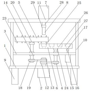
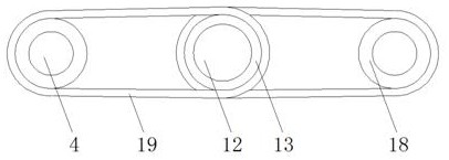
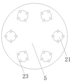
[0029] as attached Figure 1-5As shown, a motor rotor shaft press-in equipment, including a base 1, a motor 2, a fixed plate 3, a driven shaft 4, a bearing plate 5, a bearing plate 2 6, a hydraulic cylinder 7 and a pressure rod 8, is characterized in that : the base 1 is arranged on the support 9, a column 10 is vertically arranged on the base 1, and a top plate 11 is arranged on the top of the column 10, and the base 1 is connected with the support 9 and the column 10 by welding to strengthen the base 1 The connection strength with the bracket 9 and the column 10, and then improve the structural strength of the press-in equipment, the motor 2 is arranged on the base 1, and the motor 2 is provided with a transmission shaft 12, and the transmission shaft 12 is vertically connected from the top of the base 1 Stretch out, and be provided with driving wheel 13 on transmission shaft 12, described fixed plate 3 is arranged between column 10 and column 10, and is provided with bearin...

Embodiment 2

[0044] as attached Image 6 Shown: a motor rotor shaft press-in equipment, including a base 1, a motor 2, a fixed plate 3, a driven shaft 4, a bearing plate 5, a bearing plate 2 6, a hydraulic cylinder 7 and a pressure rod 8, which is characterized in that : the base 1 is arranged on the support 9, a column 10 is vertically arranged on the base 1, and a top plate 11 is arranged on the top of the column 10, and the base 1 is connected with the support 9 and the column 10 by welding to strengthen the base 1 The connection strength with the bracket 9 and the column 10, and then improve the structural strength of the press-in equipment, the motor 2 is arranged on the base 1, and the motor 2 is provided with a transmission shaft 12, and the transmission shaft 12 is vertically connected from the top of the base 1 Stretch out, and be provided with driving wheel 13 on transmission shaft 12, described fixed plate 3 is arranged between column 10 and column 10, and is provided with beari...


PUM


Abstract

The invention discloses a motor rotor rotating shaft press-in device which comprises a base, a motor, a fixing plate, a driven shaft, a first bearing plate, a second bearing plate, a first hydraulic cylinder and a pressing rod and is characterized in that the base is arranged on a support, the motor is arranged on the base, the fixing plate is arranged between stand columns. The driven shaft vertically penetrates through a bearing, the first bearing plate is arranged on the driven shaft through a first mounting ring, the second bearing plate is arranged on the driven shaft through a second mounting ring, the first hydraulic cylinder is arranged on a top plate, a first piston rod is arranged on the first hydraulic cylinder, a third mounting ring is arranged on the pressing rod, and the third mounting ring is mounted on the first piston rod. Fastening rods are arranged in a first bearing groove in the first bearing plate through springs, the fastening rods are arranged to be of an arc-shaped structure, a rotor rotating shaft is placed between the fastening rods in the first bearing groove, and the stability of the rotating shaft between the fastening rods is improved.

Description

technical field [0001] The invention relates to the technical field of motor rotors, in particular to a press-fitting device for a rotor shaft of a motor and an operation method thereof. Background technique [0002] At present, in the process of motor rotor processing, the assembly quality of the rotor shaft and the rotor directly affects the working efficiency of the rotor. Most of the existing methods are to press the rotor shaft into the rotor. For example, the patent application number 201921636246.2 discloses a motor rotor shaft Press-in equipment, which solves the problem of low efficiency of manual press-in work, but there are problems that only one rotor can be pressed in at a time, the level of mechanization is not high, the scope of application is small, and the stability of the rotor during assembly is not good. . Contents of the invention [0003] The purpose of the present invention is to overcome the problems existing in the existing rotor shaft press-in de...

Claims


Application Information

Patent Timeline
Patent Type & Authority Applications(China)
IPC IPC(8): H02K15/00H02K15/02
CPCH02K15/00H02K15/02
Inventor 徐红耀王建良
Owner NANLING LIANG POWER TOOLS
Learn More