
A power supply box externally connected with a self-triggering heat dissipation structure

A technology of heat dissipation structure and power supply box, applied in the direction of electrical components, power electronics modification, output power conversion device, etc., can solve the problems of limited heat dissipation effect, shortened service life, dusty power supply box, etc., to improve trigger accuracy , expand the cooling area, improve the effect of cooling effect

Active Publication Date: 2021-11-12
南通锦涵电器科技有限公司
View PDF3 Cites 0 Cited by
  • Summary
  • Abstract
  • Description
  • Claims
  • Application Information

AI Technical Summary

Problems solved by technology

[0003] Traditional power boxes are mostly closed structures, and the heat generated is accumulated in the power box and is not easy to dissipate. The components of the switching power supply work in a high temperature environment for a long time, which will greatly shorten the service life and even affect the working stability of the switching power supply.
[0004] In order to improve the heat dissipation of the power supply box, in the prior art, heat dissipation holes, external heat dissipation strips or cooling fans are usually provided on the power supply box. There is a lot of dust in the power box, which reduces the dustproof performance of the power box itself to a certain extent.

Method used


Image

  • A power supply box externally connected with a self-triggering heat dissipation structure
  • A power supply box externally connected with a self-triggering heat dissipation structure
  • A power supply box externally connected with a self-triggering heat dissipation structure

Examples


Embodiment 1

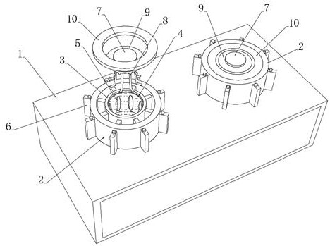
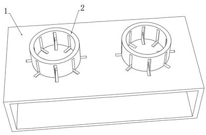
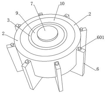
[0043] see Figure 1-3 , a power supply box externally connected with a self-triggering heat dissipation structure, including a power supply box body 1, a pair of water-cooled radiators are arranged on the power box body 1, and the water-cooled radiator includes water-cooled tubes 3 and radiating tubes 2 arranged inside and outside to dissipate heat The outer wall of the tube 2 is annularly embedded with a plurality of cooling plates 6 , and the outer wall of the cooling tube 2 is provided with an embedded cavity extending to the bottom thereof for installing the cooling plates 6 , and the inner ends of the plurality of cooling plates 6 extend to the outside of the water cooling tube 3 At the end wall, the lower ends of multiple cooling plates 6 extend to the inner side of the power box body 1, and the high temperature at the power box body 1 is transmitted outward by using the matching structure of the cooling tube 2, the water cooling tube 3 and the plurality of cooling plate...


PUM


Abstract

The invention discloses a power supply box externally connected with a self-triggering heat dissipation structure, which belongs to the field of power supply box heat dissipation. By adding a pair of water-cooled heat dissipation bodies on the power supply box body, the lower ends of multiple heat dissipation plates extend into the power supply box body for normal heat dissipation. , when the temperature of the power box body is too high, the high temperature is transmitted to the heat conduction plate through the heat dissipation plate, and the thermal deformation rod returns to the spring phase state due to the high temperature, and the thermal deformation rod shrinks and pulls the heat conduction plate to move to the side of the deformable capsule layer, and multiple deformable capsule layers Squeezed into the water-cooled tube to expand and expand, on the one hand, the heat conduction plate can be attached to the deformation bag layer to extend into the cooling liquid, and the cooling area can be expanded, and the cooling plate can be cooled by using the mutual contact with the cooling liquid, so as to promote the cooling of the power supply box. The cooling of the main body, on the other hand, after the deformation capsule layer is inwardly close to the heat conducting rod, when one of the contact pieces one and the second contact piece are in contact, the semiconductor cooling piece is intelligently and autonomously triggered to cool the coolant, further and directly and effectively improving Cooling effect.

Description

technical field [0001] The invention relates to the technical field of heat dissipation of a power supply box, and more specifically relates to a power supply box externally connected with a self-triggering heat dissipation structure. Background technique [0002] The power supply box is a device for storing the power supply, which prevents the power supply from being exposed to damage or theft, and the power supply box can be used to install the power supply in many occasions, expanding the scope of use of the power supply. [0003] Traditional power boxes are mostly closed structures, and the heat generated is accumulated in the power box and is not easy to dissipate. The components of the switching power supply work in a high temperature environment for a long time, which will greatly shorten the service life and even affect the working stability of the switching power supply. [0004] In order to improve the heat dissipation of the power supply box, in the prior art, hea...

Claims


Application Information

Patent Timeline
Patent Type & Authority Patents(China)
IPC IPC(8): H02M1/00H05K7/20
CPCH02M1/00H05K7/20927H05K7/209H05K7/2089H05K7/20509H05K7/20454
Inventor 周锦权
Owner 南通锦涵电器科技有限公司
Learn More