Anti-blocking type water storage agricultural irrigation intelligent device

An intelligent device, agricultural irrigation technology, applied in watering devices, water supply devices, drinking water devices, etc., can solve the problems affecting the overall use of the irrigation system and the blockage of the water storage tank, so as to achieve solid growth, prevent blockage, and save water. The effect of resources

Inactive Publication Date: 2021-10-08
孙耀军
View PDF0 Cites 3 Cited by
  • Summary
  • Abstract
  • Description
  • Claims
  • Application Information

AI Technical Summary

Problems solved by technology

[0005] The purpose of the present invention is to solve the problem in the prior art that the water outlet of the water storage tank of the irrigation system is prone to blockage, which affects the overall use of the irrigation system, and proposes an anti-blocking water storage intelligent agricultural irrigation device

Method used


Image

  • Anti-blocking type water storage agricultural irrigation intelligent device
  • Anti-blocking type water storage agricultural irrigation intelligent device
  • Anti-blocking type water storage agricultural irrigation intelligent device

Examples


Embodiment 1

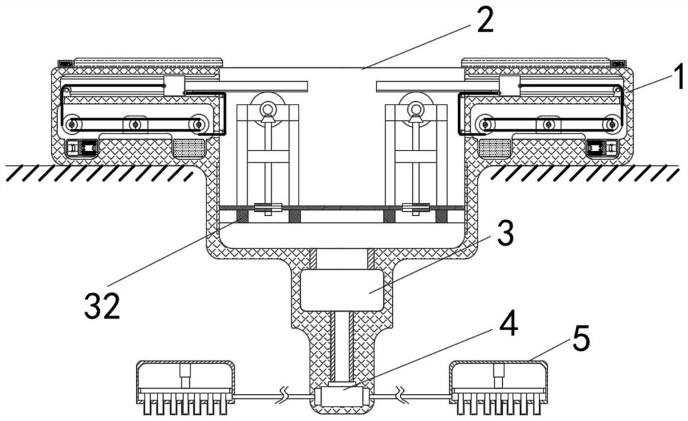
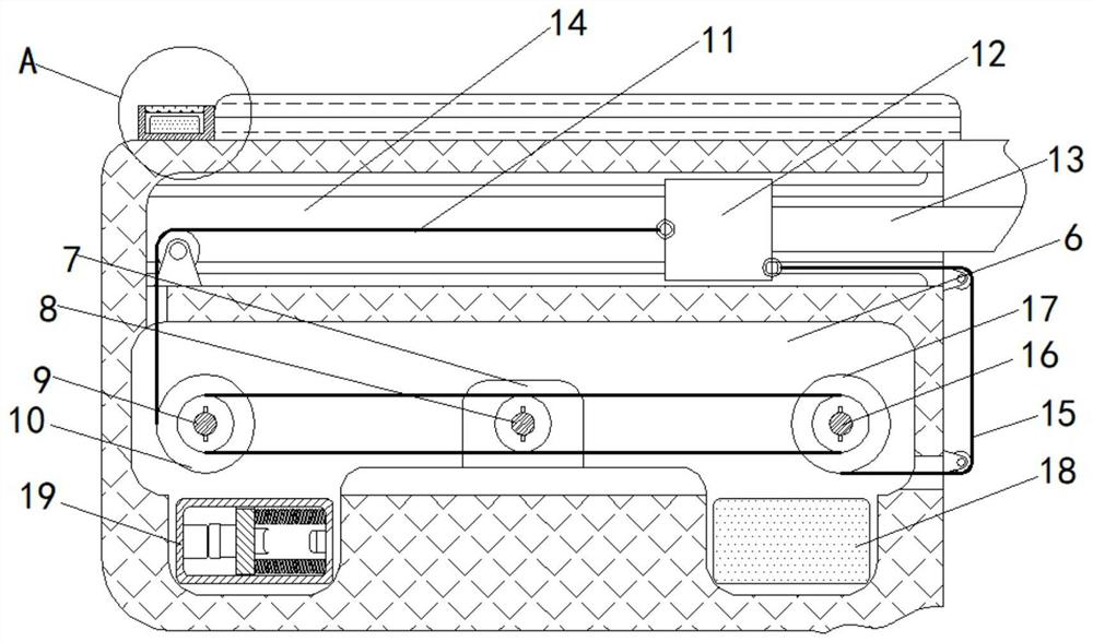
[0031] like figure 1 , Image 6 An anti-blocking water storage agricultural irrigation intelligent device includes a casing 1, a water storage tank 2 is opened on the upper surface of the casing 1, and cavities 6 are opened on both sides of the casing 1, so The housing 1 is provided with a receiving groove 14 , a moving block 12 is slidably installed in the receiving groove 14 , a cover plate 13 is fixed on the moving block 12 , and a rack 31 is fixedly installed on the lower part of the cover plate 13 . A filter bracket 32 ​​is fixedly installed inside the water storage tank 2 , a support plate 33 is installed on the filter bracket 32 ​​, a positioning frame 34 is fixed on the support plate 33 , and a horizontal shaft 35 is installed on the positioning frame 34 . A transmission gear 36 is installed on the horizontal shaft 35, the transmission gear 36 meshes with the rack 31, a first bevel gear 37 is installed on one end of the horizontal shaft 35, and a drain hole 38 is arra...

Embodiment 2

[0034] as attached figure 1 to the attached Image 6 shown:

[0035] On the basis of Embodiment 1, a motor 7 located at the cavity 6 is fixedly installed inside the casing 1, an output shaft 8 is fixedly sleeved on the output end of the motor 7, and the output shaft 8 is connected with a first transmission shaft through a belt drive 9, the outer wall of the first transmission shaft 9 is fixedly sleeved with the first wire take-up wheel 10, the outer wall of the first wire-reel pulley 10 is fixedly connected with the first wire rope 11, and the other end of the first wire rope 11 is fixedly connected with the moving block 12, The other end of the moving block 12 is fixedly connected with a second wire rope 15, the output shaft 8 is connected with a second transmission shaft 16 through a belt drive, and the outer wall of the second transmission shaft 16 is fixedly sleeved with a second wire take-up wheel 17. A receiving groove 14 is opened inside, a cover plate 13 is fixedly c...

Embodiment 3

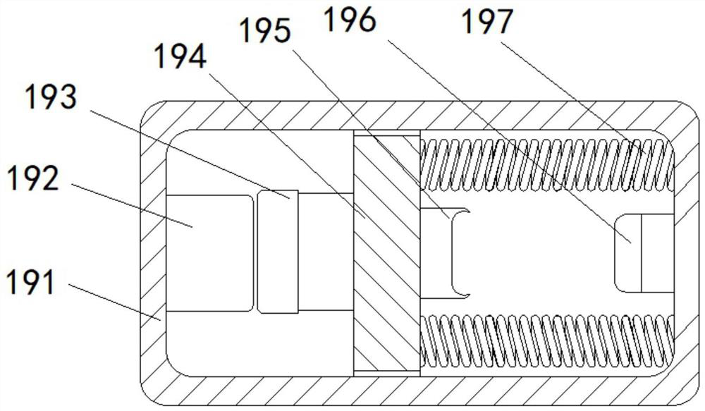
[0037] On the basis of Example 2, as attached figure 1 to the attached Image 6 Shown: the electromagnetic device 19 includes a casing 191, an electromagnet 192 is fixedly mounted on the left inner wall of the casing 191, a spring 197 is fixedly connected to the right inner wall of the casing 191, and a mounting plate 194 is fixedly connected to the other end of the spring 197, and the mounting plate 194 A magnetic block 193 is fixedly installed on the left outer wall of the mounting plate 194 , a movable contact 195 is fixedly installed on the right outer wall of the mounting plate 194 , and a contact switch 196 is fixedly installed on the right inner wall of the housing 191 .

[0038] The electromagnet 192 and the magnet block 193 are located on the same horizontal plane and correspond to each other, and the corresponding surfaces of the electromagnet 192 and the magnet block 193 have the same magnetic properties.

[0039] The movable contact 195 and the contact switch 196 ...


PUM


Abstract

The invention discloses an anti-blocking type water storage agricultural irrigation intelligent device, and relates to the technical field of irrigation. The anti-blocking type water storage agricultural irrigation intelligent device comprises a shell, the upper surface of the shell is provided with a water storage tank, the two sides of the shell are provided with cavities, during use, irrigation water is stored on the upper portion of a supporting plate, the irrigation water can flow into an irrigation box only through a water drainage hole in the supporting plate, water is filtered by a filter screen in the outflow process, impurities in the water are removed, an irrigation pipe is avoided to be blocked. When the upper portion of the filter screen is blocked, a cover plate on the upper portion of the water storage tank can be pushed to move, a rack on the lower portion of the cover plate drives a transmission gear to rotate, and then a transverse shaft and a discharging shaft are driven to rotate together. The discharging shaft rotates to drive a first fan-shaped plate and a second fan-shaped plate to rotate, and then the first fan-shaped plate and the second fan-shaped plate scrape the filter screen and push the impurities on the filter screen to move, so that it is guaranteed that the filter screen can enter the water normally, and blockage is prevented.

Description

technical field [0001] The invention relates to the technical field of irrigation, in particular to an anti-blocking water storage agricultural irrigation intelligent device. Background technique [0002] In the process of planting crops, agricultural irrigation is one of the important links in agricultural production. [0003] The existing agricultural irrigation methods can generally be divided into traditional ground irrigation, ordinary sprinkler irrigation, drip irrigation and micro-irrigation. These irrigation methods are all irrigated to the surface, and water enters the field from the surface and infiltrates the soil by gravity and capillary action. It is the most widely used and most important irrigation method at present, but the most significant disadvantage of this method is that the artificial surface is used to spray a large amount of water, which can only wet the soil surface, and most of the water flows away or is evaporated. It is easy to be lost, not only ...

Claims


Application Information

Patent Timeline
Patent Type & Authority Applications(China)
IPC IPC(8): A01G25/06E03B3/02B01D29/03B01D29/64
CPCA01G25/06E03B3/02B01D29/03B01D29/6484Y02A20/108
Inventor 孙耀军
Owner 孙耀军
Why Eureka
Try Eureka