Environment-friendly coking waste gas treatment device

A waste gas treatment device and waste gas treatment technology, applied in chemical instruments and methods, dispersed particle separation, separation methods, etc., can solve the problems of poor contact effect between coking waste gas and absorption liquid, inconvenient waste gas heat recovery, poor coking waste gas treatment effect, etc. problems, to achieve the effect of improving the exhaust gas treatment effect, improving the cooling effect, and increasing the exhaust gas treatment rate

Pending Publication Date: 2021-10-08
陈改琴
View PDF15 Cites 1 Cited by
  • Summary
  • Abstract
  • Description
  • Claims
  • Application Information

AI Technical Summary

Problems solved by technology

[0005] 1. Use the air pipe to directly inject the coking waste gas into the second box to contact the absorption liquid. Since the coking waste gas will generate more large bubbles after passing into the absorption liquid, the contact effect between the coking waste gas and the absorption liquid will be poor, which will lead to The treatment effect of coking waste gas is poor;
[0006] 2. The absorption liquid in the second box needs to be replaced regularly, and the exhaust gas treatment needs to be stopped when replacing the absorption liquid. Not only is the operation cumbersome, but also the exhaust gas treatment rate will be slow due to the long time for replacing the absorption liquid;
[0007] 3. Use high-pressure water to contact with high-temperature coking waste gas and cool down the high-temperature coking waste gas, not only the cooling effect is poor, but also it is not convenient to recover the heat of the waste gas, and the energy waste is serious

Method used


Image

  • Environment-friendly coking waste gas treatment device
  • Environment-friendly coking waste gas treatment device
  • Environment-friendly coking waste gas treatment device

Examples


Embodiment approach

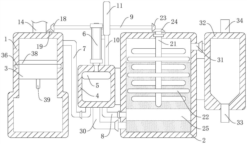
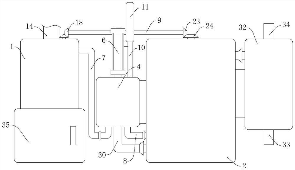
[0045] As an embodiment of the present invention, refer to figure 2 , the stirring mechanism includes a stirring rod 21 rotatably installed in the exhaust gas treatment box 2, and the top of the stirring rod 21 extends to the upper side of the exhaust gas treatment box 2, and a plurality of metal screens 22 are horizontally installed on the outer wall of the bottom end of the stirring rod 21 , the metal screen 22 can further reduce the bubbles generated by the exhaust gas in the absorption liquid, thereby facilitating the full contact between the exhaust gas and the absorption liquid, and the adjacent ends of the rotating rod 9 and the stirring rod 21 are respectively equipped with a third bevel gear 23 and a fourth bevel gear gear 24, and the third bevel gear 23 and the fourth bevel gear 24 mesh with each other.

[0046] The rotation of the rotating rod 9 can drive the third bevel gear 23, the fourth bevel gear 24 and the stirring rod 21 to rotate, and the rotation of the st...


PUM


Abstract

The invention relates to the technical field of waste gas treatment, in particular to an environment-friendly coking waste gas treatment device, which comprises a particle adsorption box and a waste gas treatment box, wherein an activated carbon adsorption layer is installed in the particle adsorption box, an absorption liquid is placed in the waste gas treatment box, a booster pump is connected between the particle adsorption box and the waste gas treatment box, a first piston and an air cylinder for driving the first piston to move up and down are arranged in the booster pump, an air inlet pipe and an air outlet pipe are mounted at the bottom end of the booster pump and connected to the particle adsorption box and the waste gas treatment box respectively, and an annular aeration plate is mounted on the inner side wall of the bottom end of the waste gas treatment box. According to the invention, small bubbles are generated in an absorption liquid by gas sprayed out of small holes in an annular aeration plate, and the absorption liquid and waste gas are stirred and mixed in cooperation with a stirring mechanism, so that the contact area of the waste gas and the absorption liquid is increased, and harmful substances in the coking waste gas can be sufficiently absorbed by the absorption liquid so as to improve the waste gas treatment effect.

Description

technical field [0001] The invention relates to the technical field of waste gas treatment, in particular to an environment-friendly coking waste gas treatment device. Background technique [0002] Exhaust gas refers to the toxic and harmful gases discharged in the process of production and life, such as chemical plants, steel plants, pharmaceutical plants, coking plants, oil refineries, etc. Coking chemical plants will produce a large amount of coking waste gas during the production process, coking waste gas Contains a large amount of harmful substances and particulate matter. If the coking waste gas is directly discharged into the atmosphere, it will cause serious pollution to the atmosphere. In order to realize the purification treatment of coking waste gas, there are coking Exhaust gas treatment device. [0003] After retrieval, Chinese Patent No. CN211864358U discloses a coking waste gas treatment device, which includes: a gas delivery device, a first treatment device,...

Claims


Application Information

Patent Timeline
IPC IPC(8): B01D53/18B01D53/04
CPCB01D53/18B01D53/0407
Inventor 陈改琴郭浩天
Owner 陈改琴
Why Eureka
Try Eureka