Stamping device for forming bearing retainer

A bearing cage and stamping device technology, applied in the field of machinery, can solve problems such as application limitations of plastic casting cages, and achieve the effects of less equipment, faster processing efficiency, and lower costs

Pending Publication Date: 2021-10-08
浙江创博汽车部件科技有限公司
View PDF0 Cites 0 Cited by
  • Summary
  • Abstract
  • Description
  • Claims
  • Application Information

AI Technical Summary

Problems solved by technology

However, due to the thermal deformation, aging and brittleness of the plastic itself, as well as some problems in the structure of the cage and the injection process, the application of the plastic casting cage is limited.

Method used


Image

  • Stamping device for forming bearing retainer
  • Stamping device for forming bearing retainer
  • Stamping device for forming bearing retainer

Examples


Embodiment Construction

[0026] The following are specific embodiments of the present invention and in conjunction with the accompanying drawings, the technical solutions of the present invention are further described, but the present invention is not limited to these embodiments.

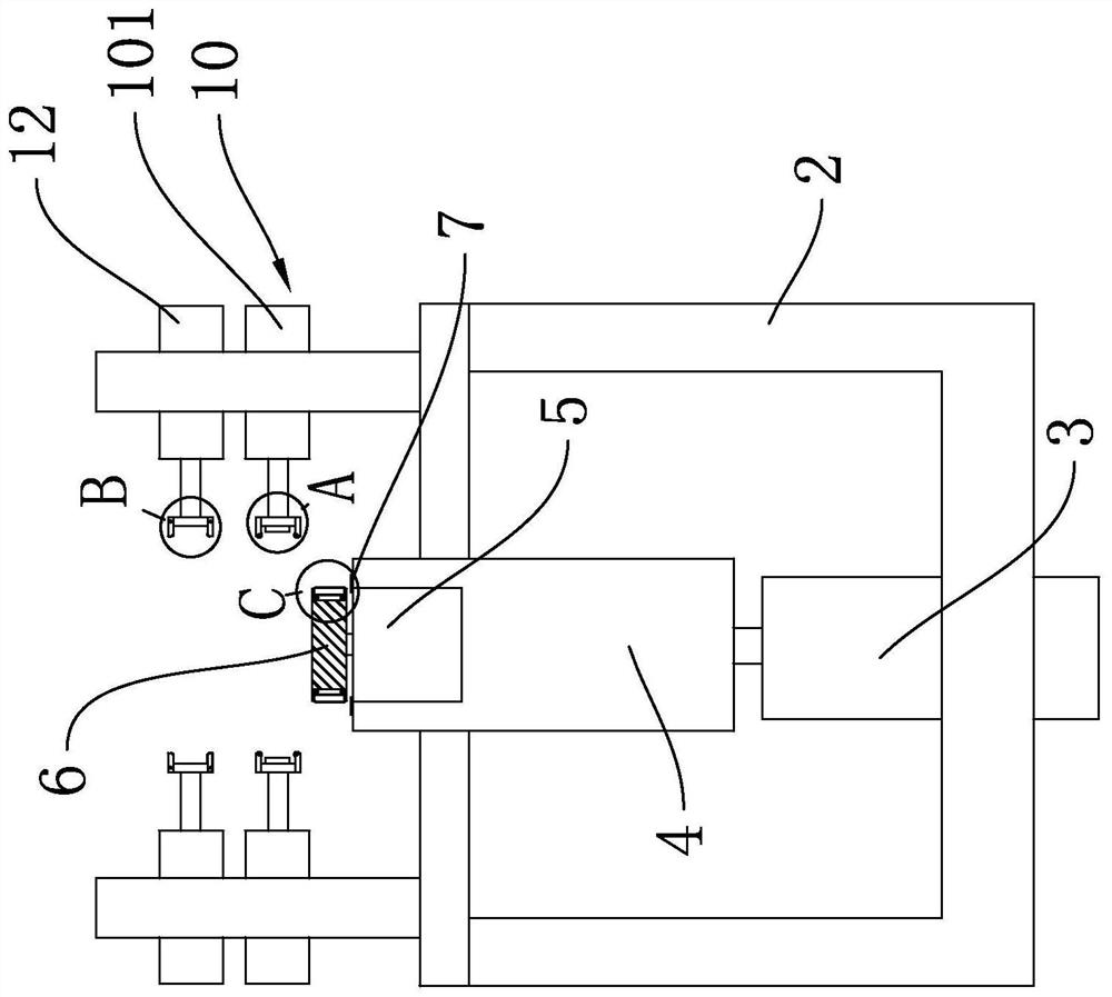
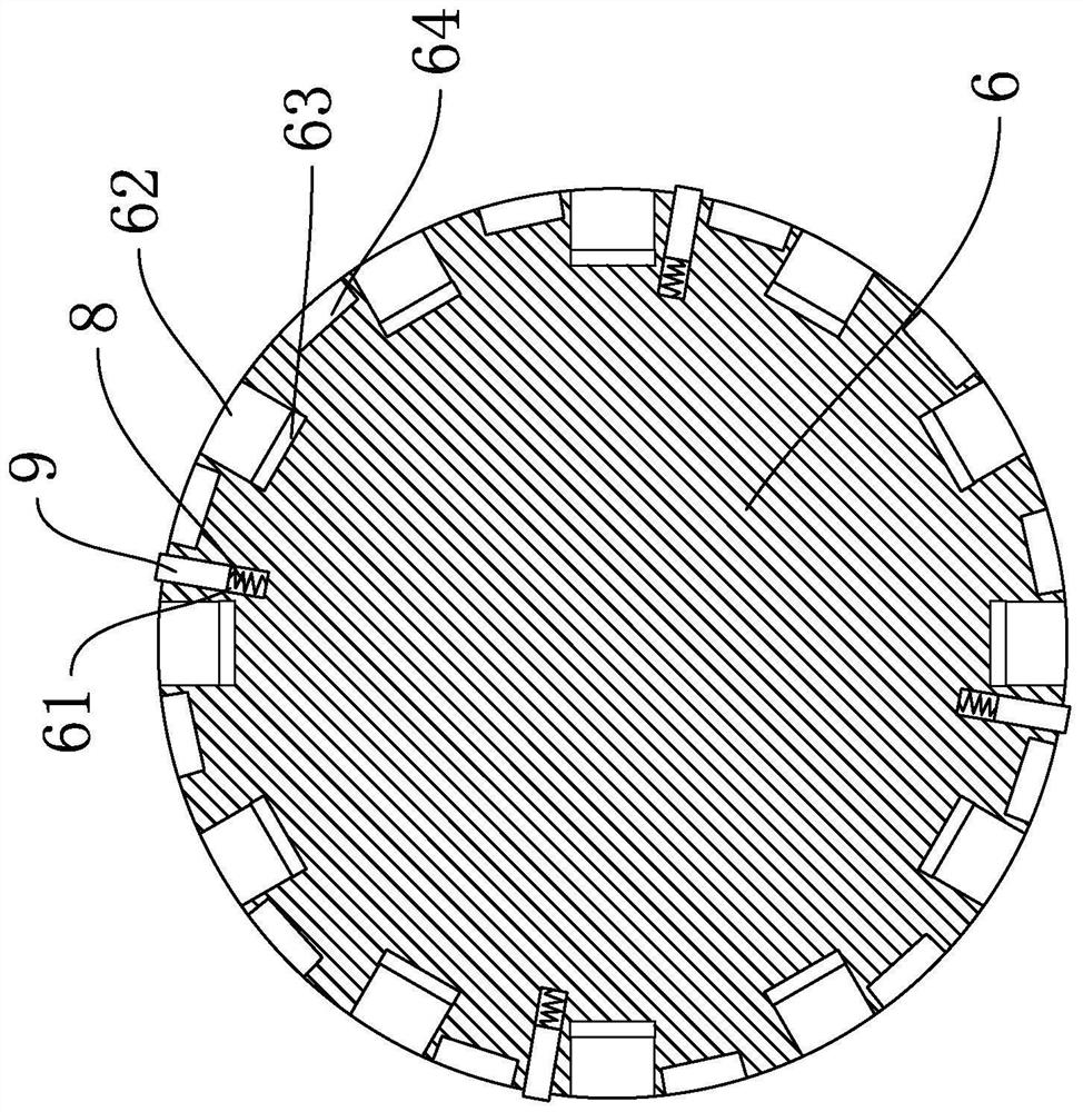
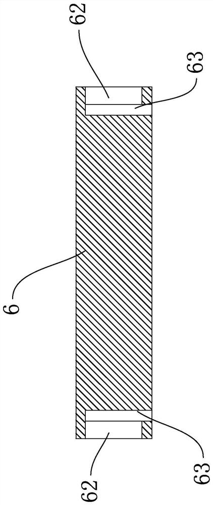
[0027] Such as Figure 1 to Figure 7 As shown, the bearing cage includes a main body a, reinforcing edges a1 arranged on the upper and lower sides of the main body a, with equidistant intervals between adjacent reinforcing edges a1, and through holes for accommodating balls are provided on the peripheral surface of the main body a a2.

[0028] A stamping device for forming a bearing cage, comprising a frame 2, a first push rod motor 3 is fixed on the frame 2, a lifting column 4 is fixed on the push rod of the first push rod motor 3, and the lifting column 4 and The frame 2 is slidably connected, the top of the lifting column 4 is fixed with a first driving motor 5, the output shaft of the first driving motor 5 is fixed wi...


PUM


Abstract

The invention provides a stamping device for forming a bearing retainer, and belongs to the technical field of machinery. The stamping device for forming the bearing retainer comprises a rack, a first push rod motor is fixed to the rack, a lifting column is fixed to a push rod of the first push rod motor, the lifting column is connected with the rack in a sliding mode, a first driving motor is fixed to the top end of the lifting column, a cylindrical rotating table is fixed to an output shaft of the first driving motor, a limiting frame is fixed to the lifting column, an annular limiting groove and a stamping groove are formed in the circumferential surface of the rotating table, a discharging hole connected with the stamping groove is formed in the rotating table, and an elastic supporting assembly used for fixing a bearing retainer blank is arranged in the limiting groove.

Description

technical field [0001] The invention belongs to the technical field of machinery, in particular to a stamping device for forming a bearing cage. Background technique [0002] The cage (that is, the bearing cage, also known as the bearing cage) refers to the bearing parts that partially wrap all or part of the rolling elements and move with them, to isolate the rolling elements, and usually guide the rolling elements and keep them in the bearing Inside. [0003] The cage is generally processed by die-casting or plastic casting. The die-casting method needs to melt the raw materials and pour them into the die-casting mold of the die-casting machine, and die-cast the cage at one time. The gate of the casting is turned on a lathe, but when die-casting an aluminum alloy cage, large-tonnage equipment is required, and the design and manufacture of the mold are complicated, and it is easy to strain the pocket of the cage during die-casting. [0004] The plastic casting method is t...

Claims


Application Information

Patent Timeline
IPC IPC(8): B21D28/24B21D19/08B21D35/00B21D43/00B21D43/14
CPCB21D43/003B21D43/14B21D28/24B21D19/08B21D35/001B21D35/002
Inventor 文承宋叶明沈敏娟宋叶华宋卓佳
Owner 浙江创博汽车部件科技有限公司
Why Eureka
Try Eureka