Polishing device for metal parts of lamps and lanterns

A technology for polishing devices and metal parts, applied in grinding/polishing safety devices, grinding drive devices, metal processing equipment, etc., can solve problems such as loud noise, low hardness of metal parts, affecting the appearance of metal parts and optical performance, etc. Achieve the effect of reducing energy consumption and ensuring polishing accuracy

Active Publication Date: 2022-01-04
南通兴胜灯具制造有限公司
View PDF0 Cites 0 Cited by
  • Summary
  • Abstract
  • Description
  • Claims
  • Application Information

AI Technical Summary

Problems solved by technology

[0002] In order to improve the overall aesthetics and optical performance of the metal parts in LED lamps, they are generally polished before assembly. At present, the existing polishing devices for metal parts in lamps still have some shortcomings when they are used, and the polishing technology is still The traditional one-moving-one-static technology is used, that is, the polishing wheel moves towards the metal parts of the lamps to be processed. Due to the limitation of use, the hardness of the metal parts for lamps is low, and the moment when the static metal parts are in contact with the polishing wheel is easily affected by the impact. The deformation occurs due to the large force, which seriously affects the appearance and optical performance of the metal parts, and during the polishing process, metal shavings and noise are likely to be generated. Although there is a dust suction mechanism around the polishing wheel, the metal shavings are still lingering in the polishing process. around the wheel, and has a large noise, which makes it difficult for the staff to observe the working status of the polishing wheel at close range. Therefore, at this stage, there is an urgent need for a lamp metal polishing device to solve the above problems

Method used


Image

  • Polishing device for metal parts of lamps and lanterns
  • Polishing device for metal parts of lamps and lanterns
  • Polishing device for metal parts of lamps and lanterns

Examples


Embodiment Construction

[0030]The following will clearly and completely describe the technical solutions in the embodiments of the present invention with reference to the accompanying drawings in the embodiments of the present invention. Obviously, the described embodiments are only some, not all, embodiments of the present invention. Based on the embodiments of the present invention, all other embodiments obtained by persons of ordinary skill in the art without making creative efforts belong to the protection scope of the present invention.

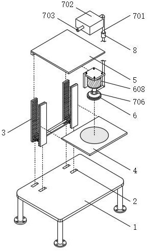
[0031] see Figure 1-9 , the lamp metal parts polishing device in the figure includes: a metal part processing table 1 for the sliding connection of the linkage assembly 3; a plurality of sliding connection ports 2, which are used to prevent the The movable stage 4 and the ceiling 5 are swayed and swayed with a plurality of sliding connection ports 2 opened on the top of the metal parts processing table 1;

[0032] Wherein, the position of the bottom of the ce...


PUM


Abstract

The invention discloses a polishing device for metal parts of lamps, which comprises: a metal part processing table used for sliding connection of linkage components; Multiple sliding connection ports that sway and sway with the ceiling are opened on the top of the metal parts processing table. This invention prevents metal shavings from escaping into the surrounding air through the cooperation of the designed linkage assembly, drainage and dust removal assembly, and air ionization assembly. In addition, the sound-proof partition brush can also isolate the noise generated between the polishing wheel and the metal parts of the lamp to be processed. On the one hand, the air flow flowing through the electric field is used, and on the other hand, the The first electrode plate and the second electrode plate provide electric energy to ionize the air flow carrying metal shavings, and the first electrode plate and the second electrode plate will absorb some dust, so as to realize the dust removal operation, and there is no need to introduce an additional power source to reduce energy consumption. consumption function.

Description

technical field [0001] The invention relates to the technical field of lighting equipment processing, in particular to a polishing device for metal parts of lamps. Background technique [0002] In order to improve the overall aesthetics and optical performance of the metal parts in LED lamps, they are generally polished before assembly. At present, the existing polishing devices for metal parts in lamps still have some shortcomings when they are used, and the polishing technology is still The traditional one-moving-one-static technology is used, that is, the polishing wheel moves towards the metal parts of the lamps to be processed. Due to the limitation of use, the hardness of the metal parts for lamps is low, and the moment when the static metal parts are in contact with the polishing wheel is easily affected by the impact. The deformation occurs due to the large force, which seriously affects the appearance and optical performance of the metal parts, and during the polish...

Claims


Application Information

Patent Timeline
Patent Type & Authority Patents(China)
IPC IPC(8): B24B29/02B24B27/02B24B55/06B24B27/00B24B41/06B24B47/12
CPCB24B29/02B24B27/02B24B55/06B24B27/0046B24B41/06B24B47/12
Inventor 颜德新
Owner 南通兴胜灯具制造有限公司
Why Eureka
Try Eureka