Wood processing device with wood chip collecting function
A processing device and wood technology, which is applied in the field of wood processing, can solve the problems of inconvenient moving of wood and labor-intensive manual movement of staff, and achieve the effects of protection, convenient cutting and stability
- Summary
- Abstract
- Description
- Claims
- Application Information
AI Technical Summary
Problems solved by technology
Method used
Image

Examples
Embodiment 1
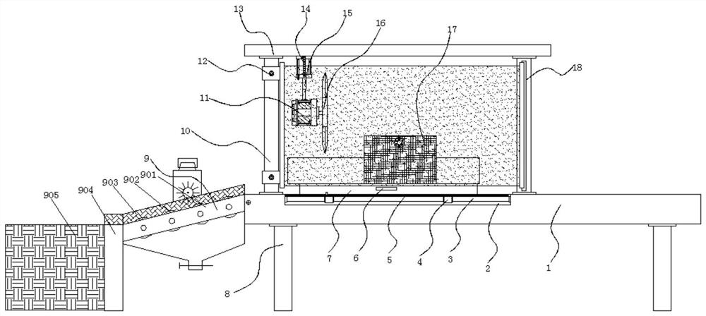
[0037] Example 1: See Figure 1-6, a wood processing device with the function of collecting sawdust, comprising a fixed table 1, four corners of the bottom of the fixed table 1 are fixedly connected with outriggers 8, and one side of the top of the fixed table 1 is fixedly connected with a first support column 10, the first A second support column 18 is fixedly connected to the fixed platform 1 on one side of the support column 10, a top plate 13 is fixedly connected to the top of the first support column 10 and the second support column 18, and a hydraulic cylinder 14 is fixedly connected to the bottom end of the top plate 13. , the model of the hydraulic cylinder 14 can be J64RT2UNIVER, the bottom end of the hydraulic cylinder 14 is fixedly connected with a telescopic rod 15, and the bottom end of the telescopic rod 15 is fixedly connected with a drive motor 11, and the model of the drive motor 11 can be Y90S-2. The output end of the motor 11 is fixedly connected with a cutt...
Embodiment 2
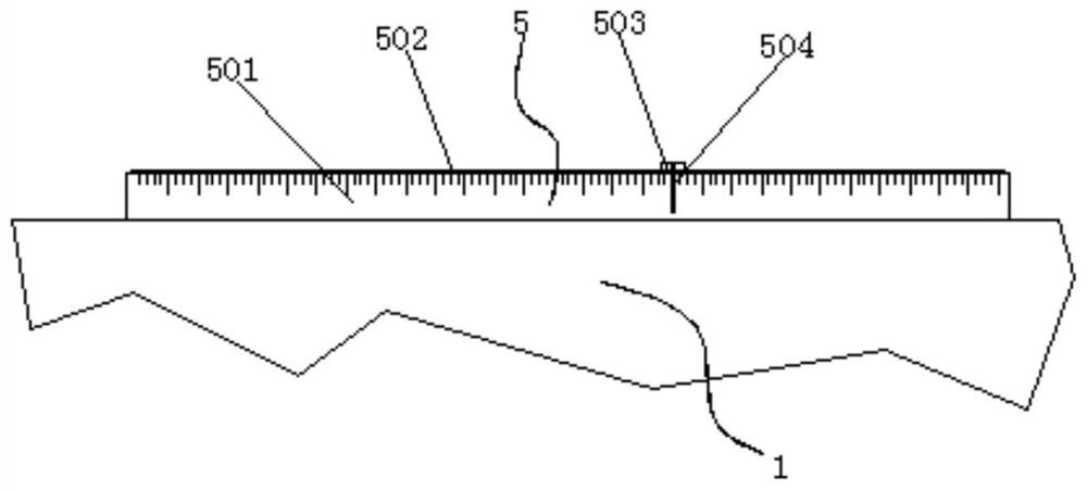
[0041] Embodiment 2: The auxiliary measuring structure 5 is composed of a fixed block 501, a chute 502, a slider 503 and an indicator rod 504. One end of the fixed block 501 is fixedly connected to one end of the fixed table 1, and the other end of the fixed block 501 is provided with a slide Slot 502, one end of the chute 502 is provided with a slider 503, and the top of the slider 503 is fixedly connected with an indicator rod 504;
[0042] The top of the fixed block 501 is provided with a scale, one end of the slider 503 is embedded in the inside of the chute 502, and the indicating rod 504 is in an "L" shape;
[0043] Specifically, such as figure 1 with figure 2 As shown, when cutting, because the top of the fixed block 501 is provided with a scale, the slider 503 embedded in the chute 502 can be moved according to the required cutting length. When moving to the corresponding scale, the indicator rod 504 will Stay above the corresponding scale, so that when cutting the ...
Embodiment 3
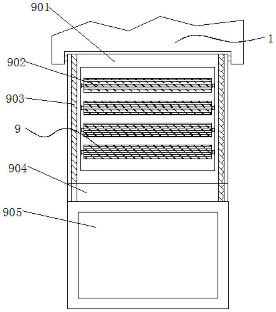
[0044] Embodiment 3: The auxiliary blanking collection structure 9 is composed of an installation frame 901, a roller shaft 902, a baffle plate 903, a base 904 and a collection box 905. One side of the installation frame 901 is hinged with one side of the fixed table 1. The installation frame 901 A roller shaft 902 is arranged inside, a baffle plate 903 is fixedly connected to the top of the installation frame 901, a base 904 is fixedly connected to the bottom end of one side of the installation frame 901, and a collection box 905 is arranged on one side of the base 904;
[0045] There are four roller shafts 902, and the roller shafts 902 are arranged at equal intervals inside the installation frame 901;
[0046] Specifically, such as figure 1 with image 3 As shown, after the wood is cut, because the roller shafts 902 arranged at equal intervals are arranged on one side of the fixed table 1, the wood will roll into the collection box 905 on one side due to the rollability of...
PUM
 Abstract
Description
Claims
Application Information
 - R&D Engineer
- R&D Manager
- IP Professional
- Industry Leading Data Capabilities
- Powerful AI technology
- Patent DNA Extraction
Browse by: Latest US Patents, China's latest patents, Technical Efficacy Thesaurus, Application Domain, Technology Topic.
© 2024 PatSnap. All rights reserved.Legal|Privacy policy|Modern Slavery Act Transparency Statement|Sitemap