Wall-mounted wing wall combined with cast-in-place pile foundation pit supporting and construction method thereof

A technology of bored piles and foundation pit support, which is applied in foundation structure engineering, sheet pile walls, excavation, etc., can solve the problems of long construction period and high cost of foundation pit support engineering, achieve diversified construction methods, reduce Concrete waste and the effect of reducing the amount of earthwork excavation

Inactive Publication Date: 2021-10-08
ZHONGYIFENG CONSTR GRP
View PDF4 Cites 1 Cited by
  • Summary
  • Abstract
  • Description
  • Claims
  • Application Information

AI Technical Summary

Problems solved by technology

[0003] The technical problem to be solved by the present invention is to provide a wall-mounted wing wall combined with bored pile foundation pit support and its construction method, which is used to solve the problem of foundation pit support when the surrounding terrain and site conditions are limited. The problem of long construction period and high cost of protection engineering

Method used


Image

  • Wall-mounted wing wall combined with cast-in-place pile foundation pit supporting and construction method thereof
  • Wall-mounted wing wall combined with cast-in-place pile foundation pit supporting and construction method thereof
  • Wall-mounted wing wall combined with cast-in-place pile foundation pit supporting and construction method thereof

Examples


Embodiment Construction

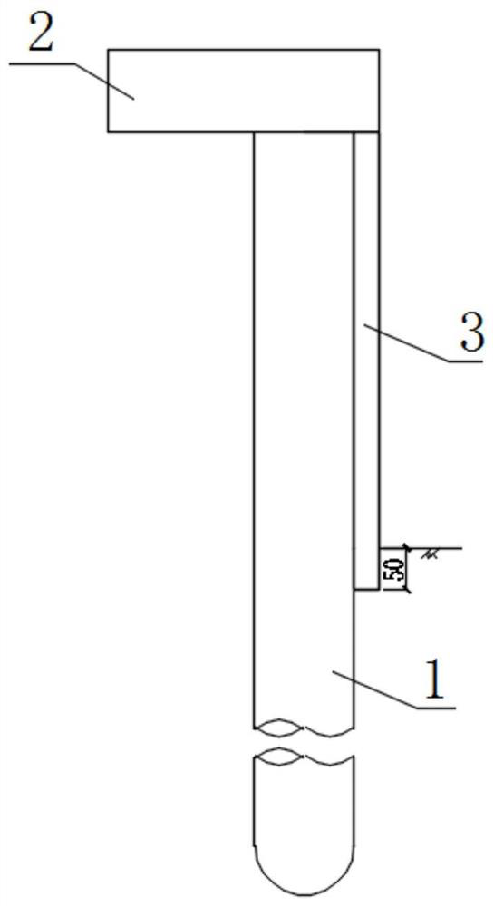
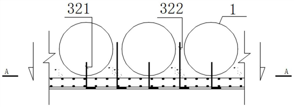
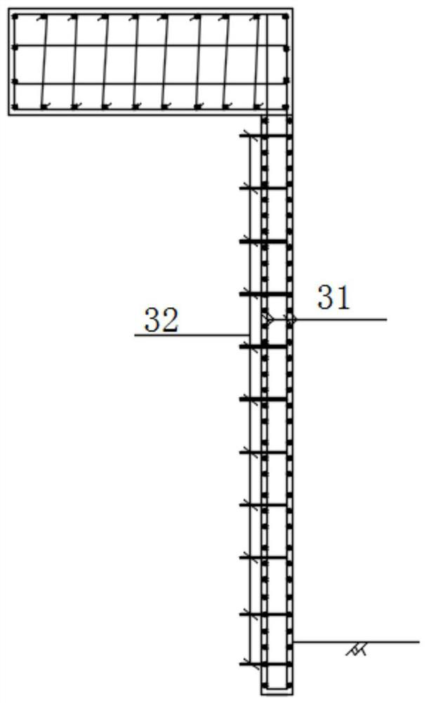
[0035] Such as Figure 1-4As shown, a wall-mounted wing wall combined with bored pile foundation pit support includes a pile 1 , a pile top platform 2 and a wall plate 3 . The wall plate 3 is located in front of the exposed surface of the cast-in-place pile 1, and the rear wall of the wall plate 3 is poured and connected with the exposed surface of the cast-in-place pile 1 to form an integrated structure, which is used as the main retaining and supporting structure of the wing wall. The pile top platform 2 is fixed on the top of the cast-in-place pile 1, and the pile top platform 2 is a cast body structure that is reinforced and reinforced on the basis of the original pile top crown beam and combined with the lower wall plate 3 as the upper support structure of the wing wall. Among them, the reinforcement is local supplementation and reinforcement of the internal reinforcement: in the vertical direction, new steel bars are newly installed at the front end of the original pile ...


PUM


Abstract

The invention discloses a wall-mounted wing wall combined with cast-in-place pile foundation pit supporting and a construction method thereof. The wall-mounted wing wall comprises cast-in-place piles, a pile top platform and wall plates; the wall plates are located in front of the exposed faces of the cast-in-place piles, and the rear walls of the wall plates are connected with the exposed faces of the cast-in-place piles in a pouring manner to serve as main soil retaining and supporting structures of the wing wall; and the pile top platform is fixed to the tops of the cast-in-place piles, and the pile top platform and the lower wall plates are combined to serve as a wing wall upper supporting structure. The construction method of the wall-mounted wing wall comprises the steps that firstly, basic plane scabbling and cleaning are conducted on original cast-in-place piles and pile top beams, then net hanging reinforcing steel bar drilling is conducted, then rear reinforcing steel bars are buried, a double-layer reinforcing steel bar net is arranged, a formwork is erected, and finally layered concrete pouring is conducted, so that the cast-in-place piles, the pile top platform and the wall plates form the integrated wall-mounted wing wall, and formwork removal and forming are conducted. The wall-mounted wing wall can adapt to the limitation of various complex terrains and site conditions, the integrity of a supporting structure and a soil retaining structure is improved, the construction period is shortened, and the construction cost is reduced.

Description

technical field [0001] The invention relates to a retaining wing wall and a construction method thereof, in particular to a wall-mounted wing wall combined with bored pile foundation pit support and a construction method thereof. Background technique [0002] At present, in the construction of water conservancy, municipal and other infrastructure projects, most foundation pit support structures are in the form of bored piles, and for foundation pit projects constructed in cities, due to the surrounding terrain and site conditions A large number of pipelines and houses and other buildings (structures) are distributed on the back side of the support structure. Based on this, the traditional construction method of the retaining wing wall constructed under the above-mentioned engineering environment needs to separately consider the supporting cast-in-place piles (such as Figure 5 The crown beam + cast-in-place pile structure shown in the previous construction), the retaining wi...

Claims


Application Information

Patent Timeline
Patent Type & Authority Applications(China)
IPC IPC(8): E02D17/04E02D5/34
CPCE02D17/04E02D5/34
Inventor 米旺曹扬杨明星
Owner ZHONGYIFENG CONSTR GRP
Why Eureka
Try Eureka