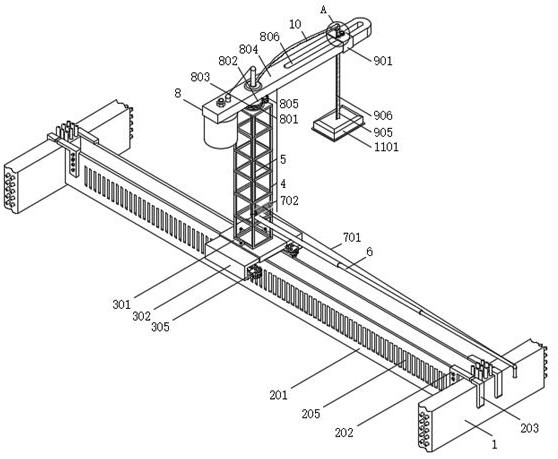
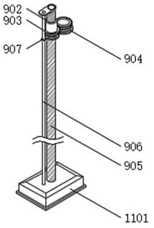
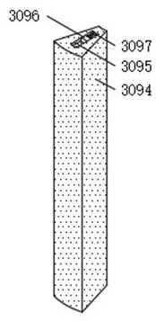
A large-area dense upper-reverse beam construction equipment

A construction equipment and large-area technology, which is applied in the fields of formwork/template/work frame, on-site preparation of building components, processing of building materials, etc. Inability to form and other problems, to achieve the effect of improving pouring and light-receiving efficiency, improving construction scope and improving construction efficiency

Active Publication Date: 2022-07-01
CHINA CONSTR SECOND ENG BUREAU LTD
View PDF0 Cites 0 Cited by
  • Summary
  • Abstract
  • Description
  • Claims
  • Application Information

AI Technical Summary

Problems solved by technology

[0002] Conventional structural beams are all under the slab, and are constructed using traditional formwork and concrete pouring procedures. The slab surface is flat and can be directly lighted. The distributing machine (concrete pouring equipment) is directly placed on the slab, free to move without obstructions, and the pump pipe is convenient to take over. There is an anti-beam on it, and the operation of the workers is limited. It is necessary to work in the beam groove formed by the anti-beam, and the distribution machine (concrete pouring equipment) and the pump pipe need to be raised and fixed in a targeted manner. Because the beam side formwork is on the plate, the formwork Reinforcement with special tools is required, and the reinforcement tools will affect the workers to collect light, place the distribution machine and the pump pipe, and after the formwork of this layer is completed, the side form reinforcement tools need to be removed quickly to carry out the formwork work of the next layer, and because Beams and slabs are not poured at the same time. After pouring the slab surface and the lower beams first, pour the upper beams before the initial setting of the slab concrete. This is because the concrete has a strong fluidity when the concrete is just poured, and the concrete cannot be blocked under the hanging formwork of the beams. Inverted beams cannot be formed, therefore, the existing technology is flawed and needs to be improved

Method used


Image

  • A large-area dense upper-reverse beam construction equipment
  • A large-area dense upper-reverse beam construction equipment
  • A large-area dense upper-reverse beam construction equipment

Examples


Embodiment Construction

[0037] In order to facilitate the understanding of the present invention, the present invention will be described in more detail below with reference to the accompanying drawings and specific embodiments. Preferred embodiments of the invention are shown in the accompanying drawings. However, the present invention may be embodied in many different forms and is not limited to the embodiments described in this specification. Rather, these embodiments are provided so that a thorough and complete understanding of the present disclosure is provided.

[0038] It should be noted that when an element is referred to as being "fixed to" another element, it can be directly on the other element or intervening elements may also be present. When an element is referred to as being "connected" to another element, it can be directly connected to the other element or intervening elements may also be present. The terms "fixed", "integrated", "left", "right" and similar expressions used in this ...


PUM


Abstract

The invention discloses a large-area intensive upper-reverse beam construction equipment, comprising an outer ring beam beam body, an upper reverse beam side formwork assembly is hung on the outer ring beam beam body, and the upper reverse beam side formwork assembly is The corresponding surface is connected with a high-position walking mobile component. In the present invention, through the mutual cooperation of the designed upper reverse beam side formwork assembly, high-position walking moving assembly, working position control assembly, working position control assembly, and concrete light-receiving assembly, the concrete placing machine can be avoided. The beam and slab after pouring will have an impact, reduce the use of the tower, effectively improve the construction scope of the concrete placing machine, and improve the construction efficiency of the concrete placing machine. It is suitable for the working environment where the sky pump cannot be used on all floors, and the In the case of a large-scale lift-type placing machine, it can directly control the amount of concrete introduced in a unit time, avoid the phenomenon of too much or too little concrete introduction in the final stage, and effectively improve the efficiency of concrete pouring and light collection.

Description

technical field [0001] The invention relates to the technical field of building construction, in particular to a large-area intensive upper-reverse beam construction equipment. Background technique [0002] Conventional structural beams are all under the slab, and are constructed using traditional formwork and concrete pouring processes. The slab surface is flat and can be directly received light. The side formwork of the beam is at the bottom of the slab, and the subsequent removal is performed under the slab, which does not affect the slab process. The placing machine (concrete pouring equipment) is directly placed on the plate, and it can move freely without any obstructions. The pump pipe is convenient to take over. When pouring, the beam and plate are poured together. There is a reverse beam on the top, and the workers are limited in operation. They need to work in the beam groove formed by the reverse beam, and the placing machine (concrete pouring equipment) and the p...

Claims


Application Information

Patent Timeline
Patent Type & Authority Patents(China)
IPC IPC(8): E04G21/04E04G21/10E04G13/04E04G21/16
CPCE04G21/04E04G21/0445E04G21/0463E04G21/0472E04G21/10E04G13/04E04G21/16E04G21/162
Inventor 秦湜孟珊王涛韩佳轩唐秉诏王果魏要坤张来喜祝海锋
Owner CHINA CONSTR SECOND ENG BUREAU LTD
Why Eureka
Try Eureka