Unlock instant, AI-driven research and patent intelligence for your innovation.

Integrated intelligent fluid pump set

A technology of intelligent fluid and pump set, which is applied to the components, pump, and pump control of the pumping device for elastic fluid, which can solve the problem that the power distribution control occupies a large space, is inconvenient to disassemble and repair the motor, and affects the heat dissipation of the inverter. problems, to achieve the effect of improving the computer room environment, the overall layout is reasonable and beautiful, and reducing the floor space.

Pending Publication Date: 2021-10-08
济南金孚瑞热能设备制造有限公司
View PDF0 Cites 0 Cited by
  • Summary
  • Abstract
  • Description
  • Claims
  • Application Information

AI Technical Summary

Problems solved by technology

[0004] The purpose of the present invention is to provide an integrated intelligent fluid pump set to solve the problem of low integration of the existing pump set in the above-mentioned background technology, usually adopting a discrete layout mode, and there is no connection relationship between each device, which is often used during installation. It will result in a long construction period, and the existing pump set power distribution control occupies a large space. The frequency converter of the water pump is placed in the distribution box, which will affect the heat dissipation of the frequency converter, and when the motor in the water pump is damaged, it is inconvenient. Maintenance personnel disassemble the motor for maintenance

Method used


Image

  • Integrated intelligent fluid pump set
  • Integrated intelligent fluid pump set
  • Integrated intelligent fluid pump set

Examples


Embodiment 1

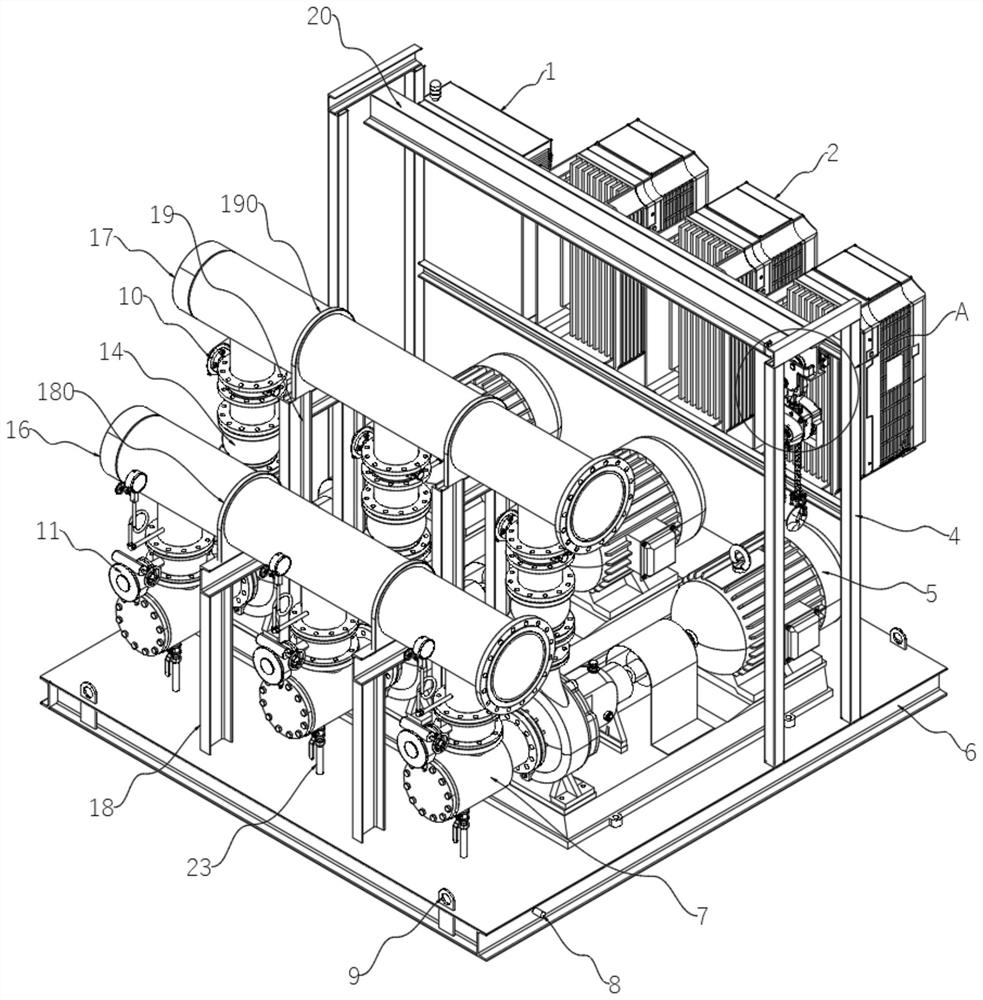
[0027] An integrated intelligent fluid pump set, including a steel structure base 6, a symmetrically distributed second U-shaped bracket 18 is arranged on the top of the steel structure base 6 and near the middle of the front edge, and the two second U-shaped brackets 18 The top is provided with a first fixing ring 180, and the water inlet main pipe 16 is supported and fixed by the second U-shaped bracket 18 and the first fixing ring 180. The two first fixing rings 180 are connected with the water inlet main pipe 16 for For the input of fluid, the bottom of the outer wall of the water inlet main pipe 16 is provided with three water inlet branch pipes 160 arranged at equal intervals, and the surface of the steel structure base 6 and the position close to the rear side of the two second U-shaped brackets 18 are provided with symmetrically distributed first Three U-shaped brackets 19, the tops of the two third U-shaped brackets 19 are provided with second fixing rings 190, and the...

Embodiment 2

[0029]An integrated intelligent fluid pump set, including a steel structure base 6, a symmetrically distributed second U-shaped bracket 18 is arranged on the top of the steel structure base 6 and near the middle of the front edge, and the two second U-shaped brackets 18 The top is provided with a first fixing ring 180, and the water inlet main pipe 16 is supported and fixed by the second U-shaped bracket 18 and the first fixing ring 180. The two first fixing rings 180 are connected with the water inlet main pipe 16 for For the input of fluid, the bottom of the outer wall of the water inlet main pipe 16 is provided with three water inlet branch pipes 160 arranged at equal intervals, and the surface of the steel structure base 6 and the position close to the rear side of the two second U-shaped brackets 18 are provided with symmetrically distributed first Three U-shaped brackets 19, the tops of the two third U-shaped brackets 19 are provided with second fixing rings 190, and the ...

Embodiment 3

[0032] An integrated intelligent fluid pump set, including a steel structure base 6, a symmetrically distributed second U-shaped bracket 18 is arranged on the top of the steel structure base 6 and near the middle of the front edge, and the two second U-shaped brackets 18 The top is provided with a first fixing ring 180, and the water inlet main pipe 16 is supported and fixed by the second U-shaped bracket 18 and the first fixing ring 180. The two first fixing rings 180 are connected with the water inlet main pipe 16 for For the input of fluid, the bottom of the outer wall of the water inlet main pipe 16 is provided with three water inlet branch pipes 160 arranged at equal intervals, and the surface of the steel structure base 6 and the position close to the rear side of the two second U-shaped brackets 18 are provided with symmetrically distributed first Three U-shaped brackets 19, the tops of the two third U-shaped brackets 19 are provided with second fixing rings 190, and the...


PUM


Abstract

The invention relates to the technical field of fluid pump sets, in particular to an integrated intelligent fluid pump set which comprises a steel structure base, a water inlet main pipe and a water outlet main pipe. Three water pumps which are arranged at equal intervals are arranged on the surface, close to the rear side, of the steel structure base, and first U-shaped supports which are symmetrically distributed are arranged on the surface of the steel structure base. A lifting appliance support is arranged between the two first U-shaped supports and located in the middle of the tops, symmetrically-distributed mounting plates are horizontally arranged at the positions, close to the tops of the rear sides,between the two first U-shaped supports, and the rear sides of the two mounting plates are jointly connected with a distribution box and frequency converters. According to the integrated intelligent fluid pump set, the fluid pump set can be prefabricated and formed in a factory, the on-site construction period is shortened, the construction cost is reduced, and a lifting appliance facilitating disassembly of a water pump motor is arranged above each water pump, so that maintenance personnel can maintain the motors conveniently, hang the frequency converters and the distribution box on an external support, heat dissipation of the frequency converters is facilitated, and the floor area can be reduced and water is prevented.

Description

technical field [0001] The invention relates to the technical field of fluid pump sets, in particular to an integrated intelligent fluid pump set. Background technique [0002] A fluid pump is a machine that transports fluid or pressurizes the fluid. It transmits the mechanical energy of the prime mover or other external energy to the fluid to increase the energy of the fluid. The fluid that can be transported mainly includes water, oil, acid and alkali, emulsion, suspension, etc. Emulsions and liquid metals, etc. [0003] Existing pump sets have a low level of integration, and usually adopt a discrete layout. There is no connection between each device, which often results in a long construction period during installation, and the existing pump set has a large space for power distribution control, and the frequency conversion of the pumps The inverter is placed in the distribution box, which will affect the heat dissipation of the inverter, and when the motor in the water p...

Claims


Application Information

Patent Timeline
IPC IPC(8): F04B23/04F04B53/20F04B53/16F04B53/00F04B49/10F04B49/00
CPCF04B23/04F04B53/20F04B53/16F04B53/00F04B49/10F04B49/00
Inventor 李涛贾竣超许杨张公安牛孝岭尚弘生刘婷
Owner 济南金孚瑞热能设备制造有限公司